Optimizing H-Beam Bridge Truss Production Through High-Definition Plasma Cutting
In the domain of heavy structural engineering, the fabrication of bridge trusses demands a level of precision that balances massive scale with minute tolerances. The transition toward narrow gap welding (NGW) for H-beam assembly has necessitated a complete re-evaluation of upstream cutting processes. Traditional methods often fail to meet the stringent geometric requirements of NGW, which relies on a highly constrained and consistent groove geometry. High-definition plasma cutting accuracy stands as the primary enabler for this workflow, providing the necessary thermal density and motion control to prepare heavy-section H-beams for high-integrity structural joints.
The Critical Role of Intersection Accuracy in Bridge Trusses
Bridge trusses are subject to complex dynamic loading, including fatigue, wind resistance, and seismic forces. The intersection where the web meets the flange of an H-beam—or where diagonal members meet chords—is the site of highest stress concentration. In a production line optimized for narrow gap welding, the fit-up of these intersections must be nearly perfect. Even a 1mm deviation in the cut path can lead to variations in the root opening, which compromises the stability of the narrow gap welding arc and leads to volumetric weld defects.
Modern plasma systems utilize sophisticated CNC interpolation to maintain consistent torch-to-workpiece distances. By employing advanced Arc Voltage Control (AVC), the plasma torch dynamically adjusts its height based on real-time feedback from the electrical characteristics of the plasma arc. This ensures that even if the H-beam flange has slight mill-scale irregularities or surface warping, the resulting cut remains perpendicular and dimensionally true. for Bridge Trusses, this means that the web-to-flange fit-up is tight enough to support the specific shielding gas dynamics required for narrow-gap processes.
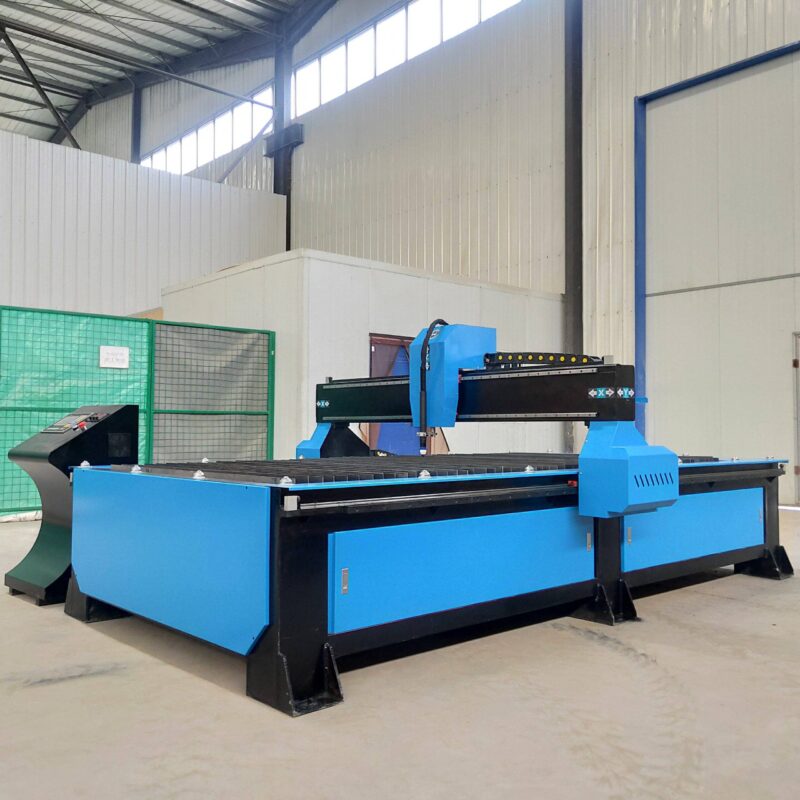
Advanced Beveling for Narrow Gap Welding Preparation
The primary advantage of narrow gap welding in bridge construction is the significant reduction in weld metal volume and the decreased heat-affected zone (HAZ). However, this process is entirely dependent on the quality of the narrow gap welding preparation performed by the plasma cutting station. Traditional V-grooves require wide angles that consume excessive consumables and time; conversely, the narrow gap approach requires a steep-walled U-groove or a very narrow V-groove, often with angles as low as 3 to 5 degrees.
Five-Axis Plasma Kinematics
Achieving these steep bevels on heavy H-beam sections requires a five-axis plasma head. This kinematic system allows the torch to tilt and rotate simultaneously, creating complex geometries such as variable bevels along a single edge. In bridge truss fabrication, where beams may meet at non-orthogonal angles, the ability to plasma-cut a “K” or “X” bevel with a consistent root face is essential. The plasma arc’s energy density allows it to penetrate through the full thickness of the web, providing a clean, dross-free surface that requires minimal post-cut grinding before moving to the welding station.
Thermal Profile and HAZ Management
Industrial engineers must account for the Heat Affected Zone (HAZ) when selecting cutting parameters. While plasma is a thermal process, high-definition systems utilize a constrained arc that narrows the thermal footprint. In the context of bridge truss fabrication, maintaining the metallurgical integrity of the base steel (often high-strength low-alloy or weathered steel) is paramount. By optimizing cutting speeds and gas selection (such as oxygen-plasma for carbon steel), the plasma system ensures that the edges of the H-beam are not over-hardened, which prevents hydrogen-induced cracking during the subsequent narrow gap welding pass.
Operational Reliability: The Case for Low-Maintenance Plasma Systems
In a high-throughput H-Beam Production Line, downtime is the single greatest threat to profitability. Bridge projects involve thousands of tons of steel, and any interruption in the cutting phase creates a bottleneck that affects the entire assembly sequence. Plasma cutting systems are engineered for the rugged environments typical of heavy structural shops, offering a significantly lower maintenance profile than alternative high-energy beam technologies.
Consumable Longevity and Robustness
The core of a plasma system’s reliability lies in its consumable design. Modern electrode and nozzle cooling systems allow for extended duty cycles, often lasting for hundreds of pierces. Unlike more sensitive optical systems, plasma torches are resilient to the dust, vibration, and metallic particulates inherent in H-beam handling. For an industrial engineer, this translates to predictable maintenance intervals and a simplified spare parts inventory. The “plug-and-play” nature of plasma torches allows operators to swap consumables in seconds, ensuring the production line maintains its cadence.
Resilience in Heavy Section Processing
H-beams used in bridges often feature flange thicknesses exceeding 50mm. Plasma cutting excels in these heavy sections, where the mechanical robustness of the gantry and the torch carriage is tested. The lack of sensitive internal components at the point of cut means the system can withstand the occasional plate collision or thermal radiation from heavy-plate processing without catastrophic failure. This durability is critical for maintaining H-beam dimensional tolerance across multi-shift operations where the equipment is under constant load.
Integrating Plasma Cutting into the Digital Workflow
To achieve the level of intersection accuracy required for narrow gap welding, the plasma cutting station must be fully integrated with the facility’s Building Information Modeling (BIM) and CAD/CAM software. This integration eliminates manual layout errors and ensures that the “as-cut” geometry matches the “as-designed” structural model perfectly.
Real-Time Kerf Compensation
The CNC controller on a high-end plasma line automatically calculates kerf compensation based on the material thickness and gas pressure. As the torch wears, the system can adjust the path to maintain the precise width of the narrow gap groove. This level of automation is what allows bridge manufacturers to move from traditional wide-gap welding to more efficient narrow-gap techniques without risking structural failure due to poor fit-up.
Automated Nesting and Material Utilization
Beyond accuracy, plasma systems contribute to the economic efficiency of the bridge truss line through automated nesting. By optimizing the placement of web and flange components on raw plate stock, the system reduces scrap rates. In bridge projects where specialized steels are used, the cost savings from material utilization alone can justify the investment in high-definition plasma technology.
Conclusion: The Synergy of Plasma and Narrow Gap Welding
The production of H-beam bridge trusses is a complex exercise in balancing speed, cost, and structural safety. By focusing on the capabilities of high-definition plasma cutting, industrial engineers can create a foundation for successful narrow gap welding operations. The precision of the 5-axis beveling, combined with the low-maintenance requirements of the hardware, provides a reliable solution for preparing the heavy sections required in modern infrastructure. As bridge designs push toward longer spans and higher loads, the intersection accuracy provided by plasma cutting remains a non-negotiable standard in the fabrication shop.
-


Cantilever Welding Robot solution
-


GF laser cutting machine
-

P3015 plasma cutting machine
-

LFP3015 Fiber Laser Cutter
-

pipe plasma cutting machine
-
LFH 4020 Fiber Laser Cutting Machine
-
LFP4020
-

gantry plasma air cutting machine
-

3D robot cutting machine
-

8 axis plasma cutting machine
-

5 axis plasma cutting machine
-

LT360 tube laser cutting machine
-

robot welding workstation
-

SF6060 fiber laser cutting machine
Advanced Fiber Laser Tube Processing Technology
Our CNC Fiber Laser Tube Cutting systems revolutionize metal fabrication by integrating high-precision cutting, punching, and profiling into a single automated workflow. Designed for versatility, this technology handles a wide array of profiles including Round, Square, Rectangular, and Oval tubes, as well as complex L-shaped and U-shaped channels.
- Precision Punching: High-speed hole punching with micron-level accuracy, eliminating the need for mechanical drilling or die-stamping.
- Complex Profiling: Advanced 3D pathing allows for intricate interlocking joints and specialized notch cuts, ideal for structural frames.
- High Material Efficiency: Intelligent nesting software minimizes scrap, reducing raw material costs across large production runs.
- Clean Finish: Delivers oxide-free, burr-free edges that require zero secondary grinding before welding.

Seamlessly processing multiple profiles with consistent precision.
Global Delivery & Logistics



From our high-tech manufacturing facility directly to your global site. PCL WeldCut ensures secure packaging, professional handling, and reliable international logistics to safeguard your equipment throughout the entire journey.