Optimizing Shipbuilding Through Advanced H-Beam Production
In the maritime construction sector, the structural integrity of a vessel relies heavily on the precision of its skeletal framework. The H-beam, serving as a primary longitudinal or transverse stiffener, must meet rigorous dimensional tolerances to ensure hydrostatic stability and load distribution. An industrial H-Beam Production Line equipped with high-definition Plasma Cutting technology offers a specialized solution for processing these heavy sections. Unlike general construction, shipbuilding requires complex intersections and precise weld preparations to withstand cyclic loading and corrosive environments. The shift toward automated plasma processing allows shipyards to move from manual layout and cutting to a streamlined, digital workflow.
The Engineering Logic of Arc Voltage Control (AVC)
The core of a high-performance H-beam cutting system is the Arc Voltage Control (AVC). In an industrial plasma environment, the distance between the torch nozzle and the workpiece—the standoff distance—is the most critical variable affecting cut quality. AVC functions by monitoring the voltage between the electrode and the H-beam. As the distance changes due to material warping, thermal expansion, or minor mill tolerances in the beam’s flanges, the voltage fluctuates.
Real-Time Height Adjustment Mechanics
The AVC system samples the arc voltage at high frequencies, comparing it against a pre-set reference value. If the voltage increases, indicating a larger gap, the controller signals the Z-axis motor to lower the torch instantly. Conversely, a drop in voltage prompts an immediate lift. In shipbuilding, where H-beams can reach lengths of 12 to 18 meters, even a slight bow in the steel can result in a failed cut without active Arc Voltage Control. This closed-loop feedback mechanism ensures that the plasma arc remains at its optimal energy density, resulting in a consistent kerf width and a perpendicular cut face across the entire length of the section.
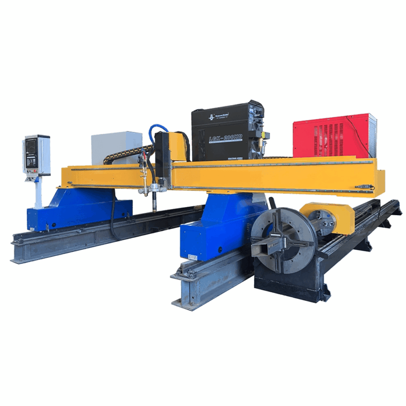
Precision in Intersection Geometry
One of the most significant challenges in ship block assembly is the “fit-up” of intersecting members. H-beams must frequently be notched, coped, or slotted to allow for the passage of piping, electrical conduits, or other structural stiffeners. Plasma cutting systems integrated into the production line utilize multi-axis robotic heads to execute these complex geometries.
Eliminating Manual Refitting
The accuracy of the intersection is dictated by the synchronization between the beam’s longitudinal movement (the X-axis) and the robotic torch’s lateral and rotational movements. By utilizing plasma, the system can achieve a high degree of intersection accuracy, typically within +/- 0.5mm. This precision is vital because any gap exceeding 1.5mm in a shipyard fit-up requires additional filler material and increases the risk of thermal distortion. By ensuring the intersection geometry is perfect at the cutting stage, the production line eliminates the need for manual grinding or “dogging” during the assembly phase on the slipway.
High-Efficiency Beveling for Weld Preparation
Shipbuilding involves heavy-gauge steel that necessitates multi-pass welding. To achieve full penetration, the edges of the H-beam flanges and webs must be beveled. Modern plasma cutting stations on the production line are capable of performing Shipbuilding plasma cutting with integrated beveling heads that can tilt up to 45 or 50 degrees.
Automated Bevel Profiles
The system can execute V, Y, X, and K-style bevels in a single pass. The AVC plays a secondary role here; as the torch tilts, the effective distance to the material changes. Advanced software compensates for this geometric shift, maintaining the arc length even during complex tilt maneuvers. This automation removes the requirement for secondary beveling processes, such as mechanical milling or manual oxy-fuel torches, which are slower and introduce significantly more heat into the part. By controlling the heat-affected zone (HAZ) through high-speed plasma travel, the metallurgical properties of the H-beam are preserved, reducing the risk of hydrogen-induced cracking in the weld zone.
Low Maintenance Requirements and Operational Longevity
From an industrial engineering perspective, the Total Cost of Ownership (TCO) is a primary metric. Plasma systems are favored in the rugged environment of a shipyard because they are inherently robust. Unlike optical-based systems that require pristine environments, plasma systems thrive in heavy industrial settings.
Simplified Consumable Management
The maintenance profile of a plasma-based H-beam line is centered on the torch consumables: the electrode, nozzle, and swirl ring. Modern high-definition plasma power sources are designed with “LongLife” technology, which manages the ramp-up and ramp-down of gas and current to minimize electrode erosion. Because the system is low maintenance, downtime is limited to scheduled consumable changes, which can be performed in minutes without specialized tools. Furthermore, the absence of complex mirrors or sensitive beam delivery components means the system is less susceptible to the vibrations and dust common in shipyards.
Data-Driven Kerf Compensation
To maintain the highest level of accuracy, the production line software incorporates kerf compensation tables. As the nozzle wears, the width of the plasma arc slightly changes. The CNC system allows operators to input wear parameters, which automatically adjust the tool path to maintain the programmed dimensions. This level of control is essential for the “snap-together” assembly methods currently being adopted by leading global shipbuilders. When every H-beam is cut with absolute fidelity to the 3D model, the overall hull assembly time is reduced by as much as 30%.
Conclusion: The Future of Structural Fabrications
The integration of Arc Voltage Control and robotic plasma cutting into the H-beam production line represents a significant leap forward in maritime engineering. By prioritizing intersection accuracy and automated beveling, shipyards can achieve a level of throughput that was previously unattainable. The robustness of the plasma process ensures that these machines remain operational in harsh conditions, providing a reliable, low-maintenance solution for the construction of the next generation of transport and naval vessels. As digital twin technology becomes the standard in shipbuilding, the ability of the plasma cutting line to translate CAD data into precise physical components becomes the cornerstone of modern naval architecture.
-


Cantilever Welding Robot solution
-


GF laser cutting machine
-

P3015 plasma cutting machine
-

LFP3015 Fiber Laser Cutter
-

pipe plasma cutting machine
-
LFH 4020 Fiber Laser Cutting Machine
-
LFP4020
-

gantry plasma air cutting machine
-

3D robot cutting machine
-

8 axis plasma cutting machine
-

5 axis plasma cutting machine
-

LT360 tube laser cutting machine
-

robot welding workstation
-

SF6060 fiber laser cutting machine
Advanced Fiber Laser Tube Processing Technology
Our CNC Fiber Laser Tube Cutting systems revolutionize metal fabrication by integrating high-precision cutting, punching, and profiling into a single automated workflow. Designed for versatility, this technology handles a wide array of profiles including Round, Square, Rectangular, and Oval tubes, as well as complex L-shaped and U-shaped channels.
- Precision Punching: High-speed hole punching with micron-level accuracy, eliminating the need for mechanical drilling or die-stamping.
- Complex Profiling: Advanced 3D pathing allows for intricate interlocking joints and specialized notch cuts, ideal for structural frames.
- High Material Efficiency: Intelligent nesting software minimizes scrap, reducing raw material costs across large production runs.
- Clean Finish: Delivers oxide-free, burr-free edges that require zero secondary grinding before welding.

Seamlessly processing multiple profiles with consistent precision.
Global Delivery & Logistics



From our high-tech manufacturing facility directly to your global site. PCL WeldCut ensures secure packaging, professional handling, and reliable international logistics to safeguard your equipment throughout the entire journey.