Optimizing Bridge Truss Fabrication through Plasma H-Beam Processing
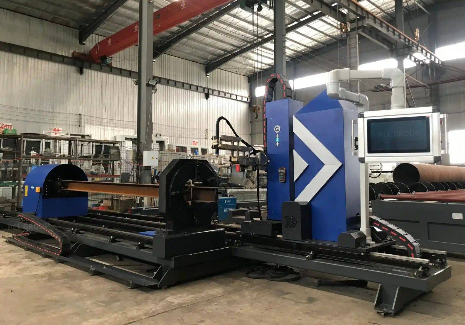
In the structural engineering sector, the fabrication of bridge trusses demands an unprecedented level of geometric precision and material integrity. The H-beam remains the primary structural element due to its high moment of inertia and load-bearing capacity. However, the transition from raw rolled steel to a finished truss component requires sophisticated cutting techniques that can handle the irregularities of heavy-duty steel sections. Utilizing a Plasma Cutting system integrated with advanced sensing technology allows manufacturers to achieve the requisite accuracy while maintaining a high throughput.
Bridge trusses are subjected to dynamic loads, thermal expansion, and environmental stress. Consequently, the fit-up of every joint is critical. The production line must account for the inherent variances in hot-rolled H-beams, such as flange out-of-squareness or web centering deviations. Traditional mechanical cutting methods often fall short in speed and versatility, whereas plasma technology provides the thermal energy density required to penetrate thick-walled sections with minimal heat-affected zones.
The Mechanics of Arc Voltage Control in H-Beam Lines
The core of a modern H-Beam Production Line is the arc voltage control (AVC) system. In plasma cutting, the distance between the torch nozzle and the workpiece—known as the standoff distance—is directly proportional to the arc voltage. During the cutting of bridge truss components, maintaining a constant standoff distance is vital for ensuring edge perpendicularity and kerf consistency.
As the plasma torch traverses the length of an H-beam, it encounters surface irregularities, scale, or slight longitudinal warping. An AVC system monitors the voltage feedback in real-time, adjusting the Z-axis lifter at millisecond intervals to compensate for these height variations. This dynamic adjustment prevents torch collisions and ensures that the plasma stream enters the material at the optimal focal point. For bridge truss nodes, where multiple beams converge, this consistency is the difference between a seamless fit and a costly secondary grinding operation.
High-Speed Sampling and Feedback Loops
Industrial-grade AVC units utilize high-speed digital signal processors to filter out electrical noise generated by the plasma power source. This ensures that the height adjustment is based on true surface topology rather than transient arc fluctuations. In the context of H-beam processing, where the torch must move across flanges and webs, the AVC must also manage the transition zones where the arc might otherwise “stretch” or “snap” due to geometry changes.
Intersection Accuracy in Complex Truss Nodes
Bridge trusses are rarely composed of simple square cuts. They involve complex intersections where diagonal members meet vertical and horizontal chords. The intersection accuracy of these cuts determines the structural efficiency of the entire bridge. Plasma cutting stations equipped with multi-axis robotic heads or specialized gantries can execute these 3D profiles with high fidelity.
The challenge in H-beam intersection lies in the “cope” or “notching” required for the web and flanges to nest perfectly. By utilizing CNC software that maps the exact dimensions of the H-beam, the plasma system calculates the intersection path. Because the AVC maintains the precise distance even during complex rotational movements of the torch head, the resulting cut follows the calculated mathematical model without deviation. This eliminates the gaps that often plague manual layout and cutting, ensuring that the structural load is distributed evenly across the joint.
Mitigating Thermal Distortion
While plasma is a thermal process, modern high-definition systems concentrate the energy into a very narrow column. When combined with precise speed control and arc voltage stability, the total heat input into the H-beam is minimized. This is crucial for Bridge Trusses where material properties must remain consistent. Reduced distortion means that the “memory” of the steel is preserved, and the beam remains straight after the cutting process, facilitating easier assembly in the field.
Advanced Beveling for High-Strength Joints
Bridge components require robust preparation for subsequent bonding processes. Beveling is the most efficient way to ensure deep penetration and structural reliability. In an H-beam production line, the plasma system must be capable of producing V, Y, K, and X-type bevels on both the flanges and the webs.
The beveling process requires the plasma torch to tilt at specific angles while maintaining the correct arc length. This is where standard height control often fails, but specialized AVC algorithms account for the angular offset. By calculating the hypotenuse of the arc path at various tilt angles, the system ensures the bevel face is uniform across the entire depth of the beam. This level of precision is mandatory for bridge trusses, where the specifications for joint preparation are governed by strict international codes such as AWS D1.5.
Single-Pass Efficiency
One of the primary advantages of using plasma for beveling in an H-beam line is the ability to perform the cut and the bevel in a single pass. Mechanical milling or grinding for beveling is time-consuming and labor-intensive. Plasma systems, however, can oscillate or tilt the torch dynamically, producing a weld-ready edge as the beam moves through the station. This significantly reduces the floor-to-floor time for each truss member.
Low Maintenance and System Longevity
From an industrial engineering perspective, the H-beam low maintenance requirement of plasma systems is a significant factor in total cost of ownership (TCO). Unlike mechanical saws that require frequent blade sharpening or complex waterjet systems that suffer from nozzle erosion and abrasive management issues, plasma systems are relatively simple.
The primary wear items in a plasma system are the consumables—the electrode and the nozzle. Modern systems feature “long-wear” technology that extends the life of these components by controlling the ramp-up and ramp-down of the gas flow and current. Furthermore, the absence of high-pressure pumps or complex optical paths means that the uptime for a plasma H-beam line is remarkably high. In a high-volume bridge fabrication facility, where downtime can derail a project timeline, the reliability of the plasma gantry is a critical asset.
Robustness in Harsh Environments
Bridge truss fabrication often occurs in semi-outdoor or dusty industrial environments. Plasma systems are designed for this. The rails, racks, and pinions of a plasma H-beam line are typically shielded and built to withstand the fine particulates associated with steel processing. The lack of sensitive internal components—compared to other high-tech cutting alternatives—makes plasma the pragmatic choice for heavy structural steel.
Conclusion: The Future of Bridge Component Manufacturing
The integration of arc voltage control into plasma H-beam production lines represents a significant leap in bridge truss fabrication technology. By focusing on the mechanical precision of the cut, the accuracy of intersections, and the efficiency of the beveling process, manufacturers can produce components that meet the highest safety and engineering standards.
The industrial engineer’s goal is always the optimization of resources, time, and quality. Through the deployment of high-definition plasma systems, the bridge construction industry achieves a balance of high throughput and extreme accuracy. As infrastructure projects grow in complexity and scale, the reliance on automated, low-maintenance, and highly accurate cutting solutions will only continue to increase, cementing plasma technology’s role as the backbone of modern structural steel fabrication.
-


LT240S tube laser cutting machine
-
LT120S tube laser cutting machine
-
Sale

Tank Fillet Welding Machine
Original price was: $1,000.00.$900.00Current price is: $900.00. -
Sale

MAK100 tube laser cutting machine
Original price was: $5,500.00.$5,000.00Current price is: $5,000.00. -

portable plasma air cutting machine
$1,200.00 -

2in1 fiber laser cutting machine
-

Air cooling Laser welding machine
-

HF h beam laser cutting machine
-

LT240 laser cutting machine
-

Laser welding machine
-


Cobot Welding Station
-

Gantry welding robot solution
-

Tracked Wheeled AGV Welding robot
-

LFH6020 Fiber laser cutting machine
-
LFP6020
-

robotic welidng machine
Advanced Fiber Laser Tube Processing Technology
Our CNC Fiber Laser Tube Cutting systems revolutionize metal fabrication by integrating high-precision cutting, punching, and profiling into a single automated workflow. Designed for versatility, this technology handles a wide array of profiles including Round, Square, Rectangular, and Oval tubes, as well as complex L-shaped and U-shaped channels.
- Precision Punching: High-speed hole punching with micron-level accuracy, eliminating the need for mechanical drilling or die-stamping.
- Complex Profiling: Advanced 3D pathing allows for intricate interlocking joints and specialized notch cuts, ideal for structural frames.
- High Material Efficiency: Intelligent nesting software minimizes scrap, reducing raw material costs across large production runs.
- Clean Finish: Delivers oxide-free, burr-free edges that require zero secondary grinding before welding.

Seamlessly processing multiple profiles with consistent precision.
Global Delivery & Logistics



From our high-tech manufacturing facility directly to your global site. PCL WeldCut ensures secure packaging, professional handling, and reliable international logistics to safeguard your equipment throughout the entire journey.