Optimization of Pressure Vessel Fabrication via Fiber Laser Systems
In the current industrial landscape, the manufacturing of pressure vessels demands a rigorous adherence to tolerances and material integrity. Traditional mechanical cutting and older thermal methods often introduce variables that necessitate costly secondary operations. However, the adoption of Fiber Laser Cutting technology has redefined the baseline for throughput and precision. From an industrial engineering perspective, the transition to high-power fiber lasers is not merely an equipment upgrade but a fundamental shift in the production workflow, specifically when dealing with heavy-gauge carbon steel and stainless steel alloys.
The primary advantage of a fiber laser in this sector lies in its beam quality. With a shorter wavelength compared to traditional CO2 lasers, fiber lasers provide higher absorption rates in metallic substrates. This results in a narrower kerf width and a highly concentrated energy density, which is critical when cutting thick-walled cylinders or dished ends. for Pressure Vessels, where every millimeter of deviation can affect the structural calculations of the shell, the precision of a fiber laser ensures that the geometric dimensions are maintained within microns of the CAD specifications.
The Mechanics of Zero-Tailing Technology
One of the most significant financial drains in heavy-duty fabrication is material waste. In traditional tube and plate processing, a significant portion of the material is left as “tailings”—the unusable ends held by the chuck or clamping system. Zero-tailing technology addresses this inefficiency through an advanced multi-chuck kinematic system. In a pressure vessel context, where the raw materials are often high-strength alloys or specialized grades, reducing the scrap rate from 10% to under 1% represents a massive shift in ROI.
Kinematic Synchronization and Support
The zero-tailing process utilizes three or four independent chucks that work in a synchronized “relay” fashion. As the laser head moves along the workpiece, the chucks shift positions dynamically. This allows the laser to cut right up to the edge of the material without losing structural support or risking collision. For the long cylindrical sections of pressure vessels, this ensures that the entire length of the raw pipe or plate is utilized, maximizing the number of components per raw unit of stock.
Integrated Workflow: Punch, Mark, and Cut
Industrial efficiency is measured by the reduction of “touches” on a workpiece. A fiber laser machine equipped for pressure vessel production performs a tripartite function: Punch-Mark-Cut. This integrated approach eliminates the need for manual layout or secondary marking stations, which are traditional sources of human error.
Automated Piercing (Punching)
Before the cut begins, the laser performs high-speed piercing. Modern fiber systems utilize frequency-modulated piercing routines that minimize the splash of molten material (dross) on the surface. This creates a clean entry point, which is vital for maintaining the fatigue strength of the pressure vessel wall. Because the pierce is controlled by the CNC, the Heat Affected Zone (HAZ) is kept to an absolute minimum, preventing localized hardening of the steel.
Precision Marking for Traceability
Traceability is a non-negotiable requirement in Pressure Vessel manufacturing. Every component must be marked with heat numbers, batch codes, and orientation guides for assembly. The fiber laser can be switched to a lower power density to etch high-contrast marks directly onto the surface. These marks are permanent and remain legible even after subsequent industrial coatings are applied. This removes the risk of misidentification during the assembly of complex vessel internals.
High-Definition Cutting
The final phase is the high-precision cut. Because the fiber laser maintains a consistent focal point and uses high-pressure nitrogen or oxygen as an assist gas, the resulting edge is remarkably smooth. This leads us to one of the most critical advantages for an industrial engineer: the elimination of secondary processes.
Eliminating the Need for Secondary Grinding
In traditional fabrication, the thermal edge left by cutting tools is often jagged or oxidized, requiring manual grinding to reach a “bright metal” finish suitable for inspection and assembly. Fiber laser cutting produces a surface finish that often meets the Ra 6.3 or even Ra 3.2 roughness standards straight off the machine. This “no grinding” capability significantly reduces labor costs and shop floor noise, while also speeding up the total production cycle.
From a metallurgical standpoint, the lack of grinding is beneficial. Grinding can introduce localized heat or mechanical stress that may create micro-fractures. By utilizing a precision machining approach via fiber laser, the edge remains chemically stable and geometrically accurate. This is particularly important for nozzle cut-outs where a perfect fit-up is required to ensure the integrity of the vessel under cyclic loading.
Thermal Management and Material Integrity
Pressure vessels are subject to strict codes such as ASME Section VIII or EN 13445. These codes regulate the allowable thermal input during fabrication. Fiber lasers, due to their high cutting speeds (often measured in meters per minute even for thick materials), transfer very little heat into the surrounding bulk material. This ensures that the mechanical properties—such as yield strength and toughness—of the pressure vessel steel are not compromised during the cutting phase.
Advanced Nesting and Efficiency
The integration of zero-tailing hardware with sophisticated nesting software allows engineers to plan complex layouts that utilize every square centimeter of material. In the context of vessel heads and cylindrical shells, nesting software can calculate the optimal path to minimize “dead travel” of the laser head, further reducing the cycle time. The software also manages the lead-in and lead-out points to ensure that the start and end of the cut do not create a stress riser in the material.
Conclusion: The Industrial Engineer’s Perspective on ROI
When evaluating the capital expenditure of a fiber laser system with Zero-tailing technology for pressure vessel production, the metrics extend beyond the initial purchase price. The ROI is calculated through three primary vectors: material savings, labor reduction, and throughput increase. By removing the need for grinding, automating the marking process, and utilizing 99% of the raw material, the cost per component drops significantly.
Furthermore, the precision offered by these machines ensures a higher “first-time right” ratio. In an industry where a single defective vessel can cost tens of thousands of dollars in scrapped material and lost time, the reliability of fiber laser technology is an essential asset. For facilities looking to scale their production of high-pressure components, the move toward automated, zero-tailing laser systems is the most logical step in achieving world-class manufacturing standards.
Technical Summary of Advantages
- Precision: Tolerance levels within +/- 0.05mm.
- Efficiency: Zero-tailing chucks eliminate nearly all material waste at the ends of the workpiece.
- Versatility: Ability to punch, mark, and cut in a single setup without manual intervention.
- Quality: Clean edges that eliminate the requirement for post-process grinding or cleaning.
- Integrity: Minimal HAZ ensures compliance with strict pressure vessel safety codes.
-


Cantilever Welding Robot solution
-


GF laser cutting machine
-

P3015 plasma cutting machine
-

LFP3015 Fiber Laser Cutter
-

pipe plasma cutting machine
-
LFH 4020 Fiber Laser Cutting Machine
-
LFP4020
-

gantry plasma air cutting machine
-

3D robot cutting machine
-

8 axis plasma cutting machine
-

5 axis plasma cutting machine
-

LT360 tube laser cutting machine
-

robot welding workstation
-

SF6060 fiber laser cutting machine
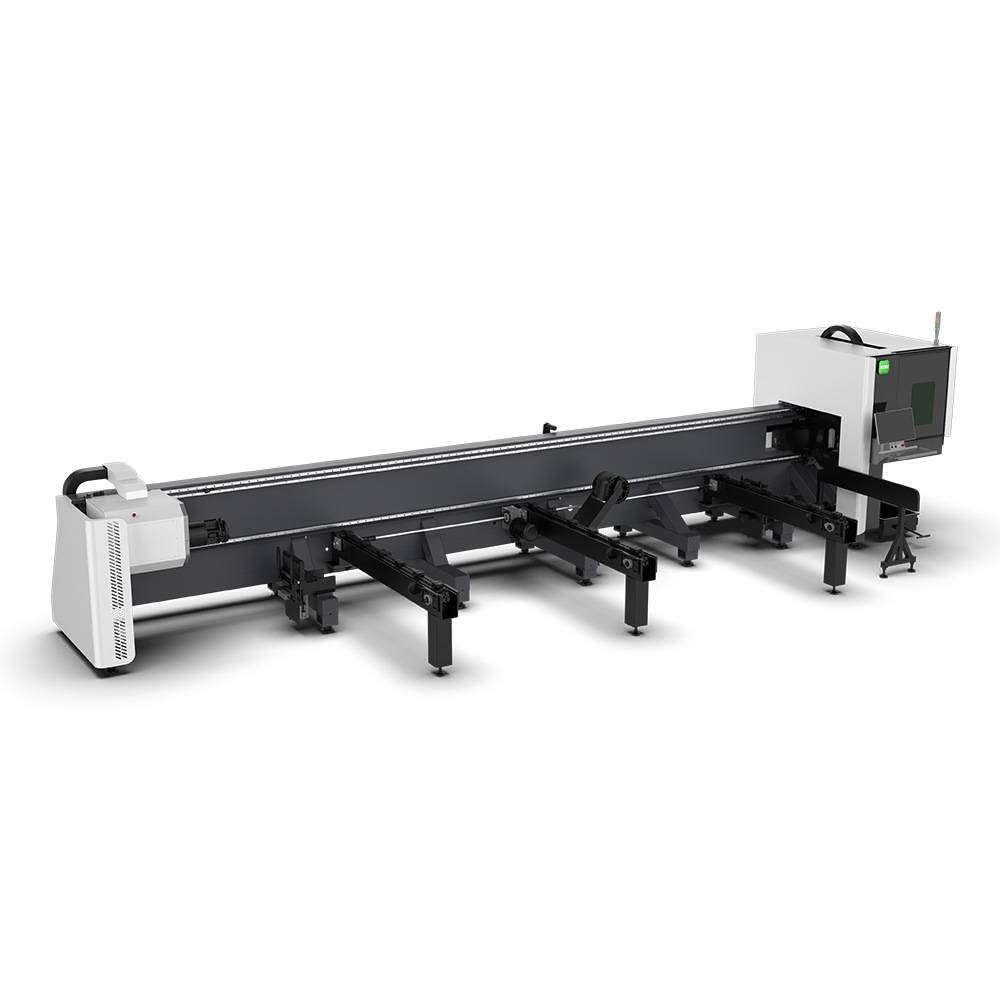
Advanced Fiber Laser Tube Processing Technology
Our CNC Fiber Laser Tube Cutting systems revolutionize metal fabrication by integrating high-precision cutting, punching, and profiling into a single automated workflow. Designed for versatility, this technology handles a wide array of profiles including Round, Square, Rectangular, and Oval tubes, as well as complex L-shaped and U-shaped channels.
- Precision Punching: High-speed hole punching with micron-level accuracy, eliminating the need for mechanical drilling or die-stamping.
- Complex Profiling: Advanced 3D pathing allows for intricate interlocking joints and specialized notch cuts, ideal for structural frames.
- High Material Efficiency: Intelligent nesting software minimizes scrap, reducing raw material costs across large production runs.
- Clean Finish: Delivers oxide-free, burr-free edges that require zero secondary grinding before welding.

Seamlessly processing multiple profiles with consistent precision.
Global Delivery & Logistics


From our high-tech manufacturing facility directly to your global site. PCL WeldCut ensures secure packaging, professional handling, and reliable international logistics to safeguard your equipment throughout the entire journey.
One thought on “Fiber Laser Cutting Machine with Zero-tailing technology for for Pressure Vessels”
The nesting software is very intuitive. Saved us a lot of carbon steel waste.