Advanced Thermal Cutting Dynamics in LNG Infrastructure
The fabrication of Liquefied Natural Gas (LNG) storage tanks and processing facilities demands a level of precision that transcends standard industrial requirements. Because these structures must withstand cryogenic temperatures (down to -162°C), the materials used—primarily 9% nickel steel and specific austenitic stainless steels—require processing methods that maintain their grain structure and mechanical properties. Industrial engineers are increasingly moving away from legacy mechanical and thermal processes in favor of high-power fiber Laser Cutting systems.
Fiber laser technology offers a unique combination of high energy density and wavelength efficiency. Unlike CO2 alternatives, the 1.06-micron wavelength of a fiber laser is absorbed more efficiently by reflective alloys, allowing for faster feed rates and a significantly narrower kerf. In the context of LNG projects, where plate thicknesses can vary significantly between the inner containment shell and secondary components, the ability to maintain a consistent, high-intensity focal point is critical for structural integrity.
The Role of Laser Seam Tracking in Large-Format Fabrication
One of the primary challenges in LNG tank construction is the physical scale of the workpieces. Large-format plates, often exceeding 12 meters in length, are prone to slight geometric deviations or “oil-canning” effects when placed on a cutting bed. Laser seam tracking solves this by utilizing a triangulation sensor that precedes the cutting head. This sensor maps the material’s surface in real-time, feeding data back to the CNC controller to adjust the Z-axis height and X-Y path instantaneously.
From an engineering perspective, seam tracking ensures that the stand-off distance remains constant. This constancy is vital for maintaining the auxiliary gas pressure (typically nitrogen or oxygen) required to clear the melt pool. Without this automated tracking, variations in the plate surface would lead to dross accumulation or incomplete cuts, both of which are unacceptable in high-pressure gas environments. By integrating this closed-loop feedback system, fabricators achieve a degree of repeatability that manual monitoring cannot match.
Eliminating Secondary Processes: The No-Grind Mandate
In traditional fabrication workflows, cutting is often followed by a labor-intensive grinding stage to remove oxides and achieve the required edge roughness for subsequent assembly. Fiber laser cutting eliminates this requirement through superior beam quality (low Beam Parameter Product). The resulting edge is characterized by a very low surface roughness (Rz value) and a negligible Heat-Affected Zone (HAZ).
For LNG applications, minimizing the HAZ is not merely an aesthetic preference; it is a metallurgical necessity. Excessive heat input can lead to carbon precipitation or localized softening in 9% nickel steel, compromising the material’s toughness at cryogenic temperatures. The high-speed nature of fiber laser cutting ensures that the dwell time of the heat source is minimized, preserving the base metal’s original specifications. By producing a weld-ready edge directly from the machine, facilities reduce labor costs by 30-40% and accelerate project timelines.
Integrated Workflow: Punch, Mark, and Cut
Efficiency in industrial engineering is measured by the reduction of “touches” on a single workpiece. Modern fiber laser centers are designed as multi-functional workstations that perform three distinct operations in a single program:
1. Precision Punching and Pilot Hole Generation
Instead of relying on separate drilling stations, the fiber laser can execute high-speed piercing routines. By modulating the laser pulse frequency and duty cycle, the system creates clean pilot holes for fasteners or subsequent processing. This ensures that the spatial relationship between the cut edge and the hole center remains within tolerances of +/- 0.1mm.
2. Permanent Part Marking and Identification
Traceability is a non-negotiable requirement for LNG Projects. Every plate must be identified by heat number, batch, and position. Using a lower power setting (etching mode), the fiber laser applies permanent barcodes, QR codes, or alphanumeric text directly onto the surface. This occurs in the same nesting sequence as the cutting, ensuring that identification is never lost during transport or assembly.
3. High-Speed Contour Cutting
The final stage is the high-velocity cut. With power levels now reaching 20kW to 60kW in industrial settings, even thick-section stainless steel is processed with a verticality that meets ISO 9013 Class 1 or 2 standards. This level of precision is fundamental when the subsequent assembly involves automated welding systems that require tight fit-ups with zero gap tolerance.
Material Integrity and Kerf Optimization
The narrow kerf width of high precision fiber lasers—often less than 0.3mm—allows for tighter nesting of parts. In the large-scale procurement cycles of LNG projects, improving material utilization by even 3-5% results in six-figure savings. Furthermore, the reduced kerf means less material is vaporized, resulting in lower particulate emissions and longer life for the filtration and dust extraction systems.
Thermal Management Strategies
Controlling the thermal gradient across a 12-meter plate is essential to prevent warping. Advanced CNC algorithms for fiber lasers utilize “bridge cutting” or “common line cutting” to distribute heat more evenly. When combined with Laser Seam Tracking, the system can compensate for any minor thermal expansion that occurs during the cutting cycle, ensuring that the last part cut on a plate is as dimensionally accurate as the first.
Auxiliary Gas Optimization
The choice of assist gas—typically Nitrogen for LNG-grade stainless steel—is handled by automated gas consoles. These systems regulate pressure and flow rate based on the material thickness detected or programmed. By maintaining an inert atmosphere in the cut zone, the fiber laser prevents oxidation, ensuring that the chromium content at the edge remains intact, which is vital for corrosion resistance in coastal LNG terminal environments.
Conclusion: The Economic and Technical Imperative
The transition to fiber laser cutting with integrated seam tracking represents a significant shift in how LNG infrastructure is built. By consolidating punching, marking, and cutting into a single, high-precision operation, engineers can guarantee the structural integrity of containment vessels while drastically reducing the time-to-completion. The elimination of post-process grinding and the reduction of the heat-affected zone directly address the metallurgical challenges of cryogenic alloys. As LNG demand continues to scale globally, the adoption of these automated, high-fidelity cutting solutions will be the distinguishing factor between projects that meet their performance benchmarks and those that succumb to the inefficiencies of legacy fabrication methods.
-


Cantilever Welding Robot solution
-


GF laser cutting machine
-

P3015 plasma cutting machine
-

LFP3015 Fiber Laser Cutter
-

pipe plasma cutting machine
-
LFH 4020 Fiber Laser Cutting Machine
-
LFP4020
-

gantry plasma air cutting machine
-

3D robot cutting machine
-

8 axis plasma cutting machine
-

5 axis plasma cutting machine
-

LT360 tube laser cutting machine
-

robot welding workstation
-

SF6060 fiber laser cutting machine
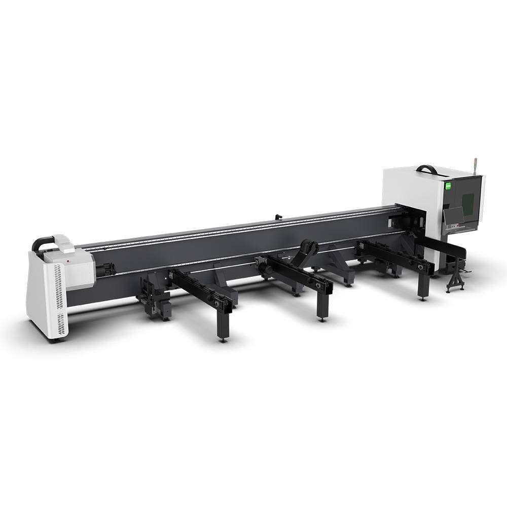
Advanced Fiber Laser Tube Processing Technology
Our CNC Fiber Laser Tube Cutting systems revolutionize metal fabrication by integrating high-precision cutting, punching, and profiling into a single automated workflow. Designed for versatility, this technology handles a wide array of profiles including Round, Square, Rectangular, and Oval tubes, as well as complex L-shaped and U-shaped channels.
- Precision Punching: High-speed hole punching with micron-level accuracy, eliminating the need for mechanical drilling or die-stamping.
- Complex Profiling: Advanced 3D pathing allows for intricate interlocking joints and specialized notch cuts, ideal for structural frames.
- High Material Efficiency: Intelligent nesting software minimizes scrap, reducing raw material costs across large production runs.
- Clean Finish: Delivers oxide-free, burr-free edges that require zero secondary grinding before welding.

Seamlessly processing multiple profiles with consistent precision.
Global Delivery & Logistics


From our high-tech manufacturing facility directly to your global site. PCL WeldCut ensures secure packaging, professional handling, and reliable international logistics to safeguard your equipment throughout the entire journey.