The Strategic Transition to Fiber Laser Technology in Naval Architecture
Shipbuilding has historically been defined by heavy-duty processes designed to handle massive steel plates and structural profiles. However, the shift toward modular block construction and thin-to-medium plate naval vessels demands a level of accuracy that traditional thermal cutting methods cannot consistently deliver. The implementation of fiber Laser Cutting represents a paradigm shift in shipyard throughput and structural integrity. Unlike older technologies, the fiber laser utilizes a solid-state gain medium, resulting in a beam with a significantly shorter wavelength (typically around 1.06 microns). This allows for superior absorption rates in marine-grade carbon steel, stainless steel, and aluminum alloys.
From an industrial engineering perspective, the primary objective is the reduction of non-value-added time. In traditional fabrication, cutting is merely the first step, often followed by extensive edge cleaning, beveling, and manual rectification. Fiber lasers eliminate these bottlenecks by producing a Heat Affected Zone (HAZ) so narrow that the metallurgical properties of the plate remain largely unchanged. This allows for direct progression to the assembly stage without the need for secondary surface preparation.
High-Density Fiber Optics: Precision at the Micron Level
The core advantage of the fiber laser lies in its beam quality, often measured by the Beam Parameter Product (BPP). A lower BPP signifies a beam that can be focused to a smaller spot size, increasing power density at the point of impact. For shipbuilders, this translates to a kerf width that is significantly thinner than any alternative. This precision is vital when nesting complex geometries or cutting interlocking notches for internal hull stiffeners. The stability of the fiber delivery system—where the light is guided through a flexible fiber optic cable rather than a series of mirrors—ensures that the power delivered to the cutting head is constant, regardless of the gantry’s position on a massive 30-meter cutting bed.
Integrated 3D Vision: Solving Spatial Deviation in Large-Scale Steel
One of the greatest challenges in large-scale maritime fabrication is material inconsistency. Large steel plates are rarely perfectly flat; they often possess inherent “bows” or surface irregularities caused by storage or initial rolling. Traditional 2D cutting heads risk collisions or focal shifts that compromise cut quality. This is where 3D vision positioning becomes a critical component of the industrial workflow. By mounting high-resolution industrial cameras and laser line sensors onto the cutting bridge, the system performs a non-contact scan of the material surface before the first pierces are made.
The vision system generates a point cloud that represents the actual spatial orientation of the workpiece. The CNC controller then uses this data to adjust the Z-axis height dynamically and compensate for any plate rotation or misalignment. This ensures that the standoff distance—the gap between the nozzle and the plate—remains constant within 0.01mm. In an industry where a single error on a large bulkhead can cost thousands of dollars in wasted material, the reliability provided by 3D vision is an essential safeguard for high-value projects.
Operational Workflow: Mark, Punch, and Cut in a Single Cycle
Efficiency in a shipyard is measured by the “arc-on” time and the minimization of plate handling. A fiber laser system with advanced software integration allows for a multi-functional processing cycle. Instead of moving a plate between different stations, the fiber laser performs marking, punching, and cutting in one continuous operation. High-precision maritime fabrication requires clear identification for downstream logistics; the laser can etch part numbers, QR codes, and alignment marks directly onto the steel at high speeds without penetrating the material.
The punching function, or “start hole” creation, is handled through high-pressure oxygen or nitrogen-assisted piercing cycles. By controlling the frequency and pulse width of the laser, the machine can create clean, vertical holes for drainage, cable routing, or fastener placement. Because the laser can switch between engraving power levels and cutting power levels in milliseconds, the transition between marking a weld line and cutting a 20mm plate is seamless, reducing the total cycle time per part by up to 40% compared to decoupled processes.
Eliminating Secondary Surface Preparation and Grinding
The most significant cost-saving factor for industrial engineers is the “ready-to-assemble” edge quality. Traditional thermal cutting often leaves dross (re-solidified metal) on the bottom of the cut or creates a hardened edge that interferes with subsequent joining processes. Fiber lasers, particularly when using high-pressure nitrogen as an assist gas, produce an oxide-free edge. This “clean cut” technology means that the edge is aesthetically and functionally superior, requiring zero manual grinding.
By removing the grinding station from the production line, shipyards reduce labor costs and eliminate the occupational hazards associated with metal dust and noise. Furthermore, the absence of dross ensures that dimensions remain true to the CAD model, allowing for tighter fit-up tolerances in block assembly. This precision is a prerequisite for thermal distortion management, as accurate fit-up reduces the amount of filler metal required and minimizes the heat input needed during the eventual joining phases.
Technical Specifications and Throughput Metrics
When calculating the Return on Investment (ROI) for a fiber laser system with 3D vision, engineers must look at the “cost per meter” of cut. Fiber lasers boast electrical conversion efficiencies of up to 40-45%, which is significantly higher than older CO2 or mechanical systems. This energy efficiency, combined with cutting speeds that can exceed 30 meters per minute on thinner gauge interior bulkheads, results in a massive increase in annual tonnage capacity. The integration of 3D vision further enhances this by reducing the setup time; the machine “finds” the plate automatically, meaning the operator does not need to spend time manually squaring the material to the machine’s coordinate system.
Enhanced Safety and Environmental Impact
Modern shipbuilding is under increasing pressure to adopt “green” manufacturing standards. Fiber laser systems contribute to this by producing fewer emissions and requiring no hazardous chemicals for surface cleaning. The precision of the 3D vision positioning also improves nesting algorithms, allowing parts to be placed closer together on a single sheet. This maximizes material utilization and reduces the volume of scrap steel that must be recycled. The fully enclosed nature of high-power laser cells also ensures that workers are protected from radiation and high-intensity light, creating a safer industrial environment.
Conclusion: The Future of High-Efficiency Ship Component Fabrication
The integration of fiber laser technology with 3D spatial awareness marks the end of the “rough cut” era in shipbuilding. By focusing on high-density energy delivery and intelligent material sensing, shipyards can produce components that are accurate to the millimeter over spans of several meters. This level of precision is not merely a luxury; it is a fundamental requirement for the next generation of modular, high-performance vessels. The elimination of post-process grinding and the consolidation of marking and cutting into a single automated stream ensures that the shipyard of the future remains competitive in a global market that values both speed and structural excellence.
-


LT240S tube laser cutting machine
-
LT120S tube laser cutting machine
-
Sale

Tank Fillet Welding Machine
Original price was: $1,000.00.$900.00Current price is: $900.00. -
Sale

MAK100 tube laser cutting machine
Original price was: $5,500.00.$5,000.00Current price is: $5,000.00. -

portable plasma air cutting machine
$1,200.00 -

2in1 fiber laser cutting machine
-

Air cooling Laser welding machine
-

HF h beam laser cutting machine
-

LT240 laser cutting machine
-

Laser welding machine
-


Cobot Welding Station
-

Gantry welding robot solution
-

Tracked Wheeled AGV Welding robot
-

LFH6020 Fiber laser cutting machine
-
LFP6020
-

robotic welidng machine
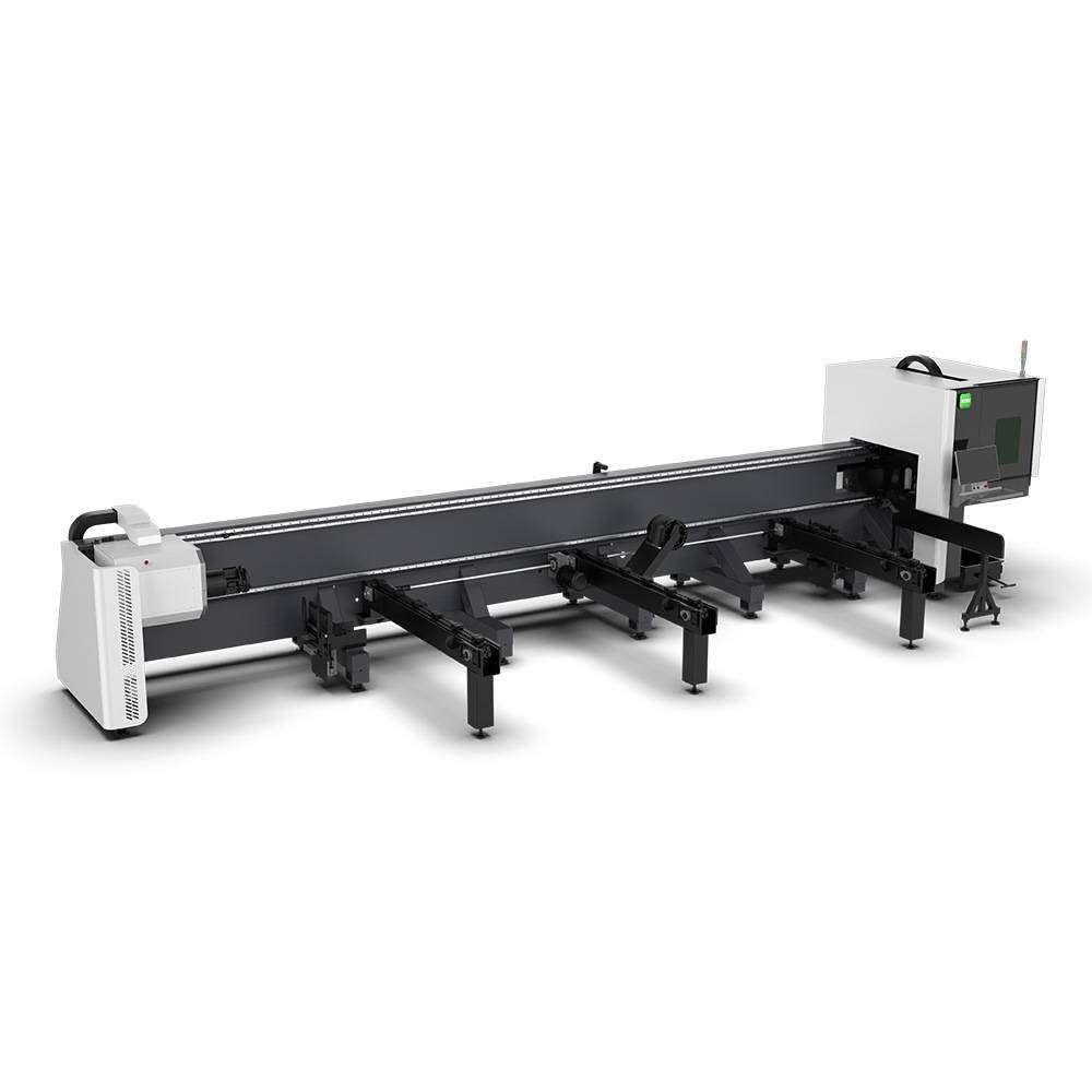
Advanced Fiber Laser Tube Processing Technology
Our CNC Fiber Laser Tube Cutting systems revolutionize metal fabrication by integrating high-precision cutting, punching, and profiling into a single automated workflow. Designed for versatility, this technology handles a wide array of profiles including Round, Square, Rectangular, and Oval tubes, as well as complex L-shaped and U-shaped channels.
- Precision Punching: High-speed hole punching with micron-level accuracy, eliminating the need for mechanical drilling or die-stamping.
- Complex Profiling: Advanced 3D pathing allows for intricate interlocking joints and specialized notch cuts, ideal for structural frames.
- High Material Efficiency: Intelligent nesting software minimizes scrap, reducing raw material costs across large production runs.
- Clean Finish: Delivers oxide-free, burr-free edges that require zero secondary grinding before welding.

Seamlessly processing multiple profiles with consistent precision.
Global Delivery & Logistics


From our high-tech manufacturing facility directly to your global site. PCL WeldCut ensures secure packaging, professional handling, and reliable international logistics to safeguard your equipment throughout the entire journey.