Technological Integration of Fiber Lasers in Maritime Engineering
The shipbuilding industry is currently undergoing a paradigm shift from traditional thermal cutting methods toward high-precision high-power fiber Laser Cutting. As an industrial engineer, the focus is on optimizing throughput while maintaining the rigorous safety standards required for seafaring vessels. The transition to fiber laser technology is not merely a change in the energy source; it is a fundamental shift in how large-scale steel plates are processed, handled, and prepared for assembly. By utilizing fiber lasers, yards can achieve a level of precision that was previously unattainable on the massive scales common in hull and deck construction.
The core advantage of the fiber laser lies in its wavelength—typically around 1.06 microns—which allows for a much smaller spot size and higher energy density compared to older CO2 counterparts. This density results in a significantly reduced Heat Affected Zone (HAZ), which is critical for maintaining the metallurgical properties of high-tensile marine steels like AH36 and DH36. Minimizing the HAZ ensures that the material does not become brittle at the cut edge, a vital requirement for the structural longevity of a ship’s hull.
Automated 3D Vision Positioning Systems
One of the most significant challenges in shipbuilding is the physical scale of the workpieces. Large steel plates, often exceeding 20 meters in length, are susceptible to inherent material stresses and physical deformations. Traditional 2D cutting systems often fail to account for the “waviness” or slight bowing of these plates when placed on a cutting bed. The implementation of automated 3D vision positioning solves this by creating a real-time digital twin of the material surface.
The 3D vision system utilizes high-speed industrial cameras and laser profilers to scan the plate before the cutting process begins. This scan generates a point cloud that maps the exact topography of the material. The machine control software then applies a transformation algorithm to the original CAD/CAM data, adjusting the laser’s focal point and trajectory in three dimensions. This ensures that the laser head maintains a constant standoff distance and perpendicular orientation to the plate surface, regardless of any physical distortion. The result is a cut that remains consistent in kerf width and angle across the entire workpiece.
The Consolidation of Punching, Marking, and Cutting
In a standard industrial workflow, plates often move between different stations for marking, hole punching, and final profile cutting. Every time a part is moved, there is a risk of compounding tolerances and labor-intensive repositioning. Modern fiber laser systems designed for Shipbuilding integrate these functions into a single continuous operation. This multi-process integration is a cornerstone of Lean manufacturing in the shipyard.
Precision Hole Punching
Fiber lasers allow for high-speed “punching” or piercing of holes with diameters equal to or even smaller than the material thickness. Because the laser can modulate its power and frequency instantaneously, it can create perfectly circular bolt holes or drainage ports without the mechanical stress associated with physical drill bits or punches. This eliminates the need for secondary drilling operations later in the assembly line.
High-Speed Surface Marking
Assembly in shipbuilding is a complex logistical puzzle involving thousands of unique parts. The fiber laser can be de-focused or run at lower power to etch assembly instructions, part numbers, and alignment lines directly onto the plate surface. This marking is permanent enough to withstand the shipyard environment but does not compromise the plate’s structural integrity. By marking directly after the 3D vision scan, the accuracy of these marks is guaranteed relative to the cut edges.
The Engineering Impact of Zero-Grinding Edge Quality
Perhaps the most compelling argument for fiber laser adoption from an operational standpoint is the achievement of zero-grinding edge quality. In traditional maritime fabrication, edges often require extensive manual grinding to remove slag, dross, or oxidation layers before they are suitable for further processing. This manual labor is not only a bottleneck but also a significant source of occupational health hazards, such as noise and metallic dust.
The high-frequency pulse and optimized gas assist (often using oxygen or nitrogen depending on material thickness) of a fiber laser produce a clean, square edge. The dross-free nature of the cut means that parts can go directly from the laser bed to the assembly area. From an industrial engineering perspective, this removes a major “non-value-added” step from the production cycle, drastically reducing the total man-hours per ton of steel processed. Furthermore, the absence of mechanical burrs improves the safety of material handlers and reduces the wear on downstream machinery.
Optimizing Material Utilization and Nesting
Fiber laser cutting facilitates extremely tight nesting layouts due to the narrow kerf width (often less than 0.5mm). When combined with 3D vision, the system can accurately detect the edges of remnant plates, allowing the software to nest new parts into scrap areas with millimeter precision. In an industry where material costs represent a significant portion of the total project budget, increasing plate utilization by even 3-5% can result in millions of dollars in annual savings for a large-scale shipyard.
Conclusion: The Future of Maritime Fabrication
The integration of fiber laser technology with 3D vision is not just an incremental improvement; it is a comprehensive solution to the dimensional inaccuracies and labor inefficiencies that have historically plagued the shipbuilding industry. By focusing on high-precision cutting, marking, and punching in a single setup, shipbuilders can ensure that every component fits perfectly during the “block assembly” phase. This level of accuracy reduces the need for onsite “fitting” and rework, which are the primary drivers of cost overruns in vessel construction.
As industrial engineers, our goal is the creation of a seamless flow from digital design to physical assembly. The fiber laser, guided by the “eyes” of 3D vision, provides the necessary bridge to achieve this. The result is a faster production cycle, a safer working environment, and a superior end product that meets the stringent demands of modern naval architecture.
-


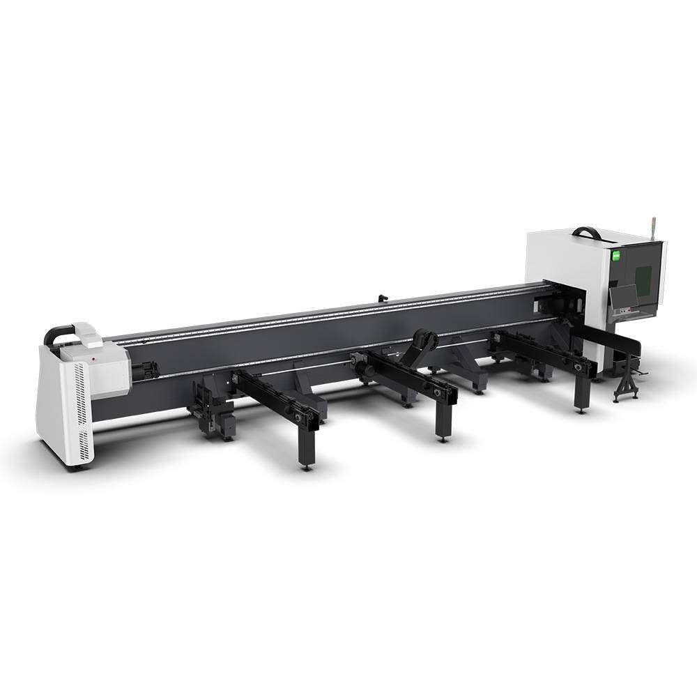
LT240S tube laser cutting machine
-
LT120S tube laser cutting machine
-
Sale

Tank Fillet Welding Machine
Original price was: $1,000.00.$900.00Current price is: $900.00. -
Sale

MAK100 tube laser cutting machine
Original price was: $5,500.00.$5,000.00Current price is: $5,000.00. -

portable plasma air cutting machine
$1,200.00 -

2in1 fiber laser cutting machine
-

Air cooling Laser welding machine
-

HF h beam laser cutting machine
-

LT240 laser cutting machine
-

Laser welding machine
-


Cobot Welding Station
-

Gantry welding robot solution
-

Tracked Wheeled AGV Welding robot
-

LFH6020 Fiber laser cutting machine
-
LFP6020
-

robotic welidng machine
Advanced Fiber Laser Tube Processing Technology
Our CNC Fiber Laser Tube Cutting systems revolutionize metal fabrication by integrating high-precision cutting, punching, and profiling into a single automated workflow. Designed for versatility, this technology handles a wide array of profiles including Round, Square, Rectangular, and Oval tubes, as well as complex L-shaped and U-shaped channels.
- Precision Punching: High-speed hole punching with micron-level accuracy, eliminating the need for mechanical drilling or die-stamping.
- Complex Profiling: Advanced 3D pathing allows for intricate interlocking joints and specialized notch cuts, ideal for structural frames.
- High Material Efficiency: Intelligent nesting software minimizes scrap, reducing raw material costs across large production runs.
- Clean Finish: Delivers oxide-free, burr-free edges that require zero secondary grinding before welding.

Seamlessly processing multiple profiles with consistent precision.
Global Delivery & Logistics


From our high-tech manufacturing facility directly to your global site. PCL WeldCut ensures secure packaging, professional handling, and reliable international logistics to safeguard your equipment throughout the entire journey.