Advanced Material Processing in Pressure Vessel Fabrication
In the contemporary industrial landscape, the fabrication of pressure vessels demands a level of precision that transcends traditional mechanical methods. The shift toward fiber Laser Cutting technology represents a fundamental pivot in how engineers approach heavy-wall carbon steel and stainless steel components. Unlike legacy thermal cutting processes, fiber lasers utilize a solid-state gain medium, resulting in a significantly smaller spot size and higher power density. This allows for an extremely narrow kerf and a minimal heat-affected zone (HAZ), which is critical for maintaining the metallurgical integrity of the vessel’s shell.
For industrial engineers, the primary objective is the reduction of Total Cycle Time (TCT). Traditional methods often involve a multi-stage process: manual marking, rough cutting, and intensive secondary grinding to reach the final dimensions and surface finish requirements. High-precision fiber lasers eliminate the grinding phase entirely. The edge quality produced by a 12kW to 30kW fiber source achieves a roughness level that meets most international standards for immediate fit-up, effectively removing a non-value-added step from the production line.
3D Vision Positioning and Spatial Calibration
One of the most significant challenges in pressure vessel manufacturing is the inherent geometric variance in large-scale components. Dished ends, whether ellipsoidal, torispherical, or hemispherical, rarely conform perfectly to their theoretical CAD models due to material spring-back and forming tolerances. This is where 3D vision positioning becomes an indispensable asset.
The system employs high-resolution industrial cameras and laser line profilers to generate a real-time point cloud of the workpiece. By comparing the “as-built” scan to the “as-designed” CAD data, the machine’s control software can perform automated path compensation. If a dished end is slightly out-of-round or has a varying crown radius, the 3D vision system recalculates the cutting trajectory in six degrees of freedom. This ensures that nozzle cut-outs and manway openings are placed with sub-millimeter accuracy relative to the actual center of the component, rather than its theoretical coordinates.
Multifunctional Workflow: Punching, Marking, and Cutting
Modern fiber laser systems designed for the pressure vessel industry are not merely cutting tools; they are integrated processing centers. The ability to execute punching (piercing), marking, and cutting in a single setup drastically reduces material handling overhead.
The marking capability is particularly vital for traceability and assembly. Using the same laser head, the system can etch heat numbers, orientation lines, and attachment locations directly onto the surface of the vessel plates. This high-speed engraving is permanent and legible, surviving subsequent blast cleaning and coating processes. Furthermore, the “punching” or precision piercing sequence is optimized through multi-stage ramping of laser power and assist gas pressure. This prevents spatter and ensures that the entry point of the cut is as clean as the exit, maintaining the structural uniformity required for high-pressure applications.
Eliminating Secondary Grinding through Precision Kerf Control
The transition to pressure vessel fabrication via fiber laser technology is often justified by the elimination of post-process cleanup. In the engineering of thick-walled vessels, the perpendicularity of the cut and the absence of dross are non-negotiable. Fiber lasers achieve this through superior beam collimation and the use of high-pressure nitrogen or oxygen assist gases.
Because the laser energy is so concentrated, the material is vaporized or blown away before it can form a significant melt pool. This results in a “ready-to-assemble” edge. For an industrial engineer, this means the removal of grinding booths from the shop floor, a reduction in abrasive consumable costs, and a significant improvement in the working environment regarding noise and metallic dust. The precision is such that even complex saddle cuts for nozzle intersections require no manual trimming to achieve the tight tolerances necessary for automated fit-up.
Technical Optimization of 5-Axis Laser Heads
To accommodate the curvature of pressure vessel heads and shells, the laser cutting machine must utilize a 5-axis or 6-axis motion system. The cutting head must maintain a constant standoff distance (focal position) relative to the fluctuating surface of the metal. Capacitive sensing integrated into the nozzle allows for real-time height adjustments, but the 3D vision system provides the macro-level orientation data.
The software integration is the backbone of this operation. Post-processors must handle the transformation of 2D flat patterns into 3D spatial paths while accounting for the angle of the laser head. This is crucial for bevel cutting—where the laser creates a V, Y, or K-shaped edge profile in preparation for the next stage of assembly. By controlling the tilt and rotation of the head during the cut, the machine produces a precise geometric profile that ensures consistent root gaps and land thicknesses across the entire circumference of the vessel.
Economic Impact and Operational Efficiency (OEE)
From an Industrial Engineering perspective, the ROI (Return on Investment) of a 3D vision-enabled fiber laser system is calculated through Overall Equipment Effectiveness (OEE). The reduction in setup time is the first major gain. Instead of manual layout and center-punching which can take hours on a large dished head, the 3D scan and alignment are completed in minutes.
Material utilization is also improved. The high precision of the laser allows for tighter nesting of components on a single plate. When cutting openings in shells, the kerf width—often less than 0.3mm—ensures that the “slug” or removed material can sometimes be repurposed for smaller fittings or test coupons, minimizing scrap. Furthermore, the reliability of fiber laser sources, which often boast a B10 life of over 100,000 hours, ensures that the machine remains a consistent link in the production chain with minimal scheduled downtime for maintenance compared to older CO2 or mechanical alternatives.
Conclusion: The Future of Vessel Preparation
The integration of fiber laser cutting with 3D Vision positioning represents the pinnacle of current fabrication technology for the pressure vessel industry. By synthesizing real-time metrology with high-energy density beams, manufacturers can achieve a level of repeatable precision that was previously impossible. The elimination of manual layout, the removal of secondary grinding, and the consolidation of marking and cutting into a single automated process drive down costs while increasing safety and quality. For the industrial engineer, these systems provide the data-driven control necessary to optimize complex manufacturing workflows and meet the rigorous demands of the global energy and processing sectors.
-


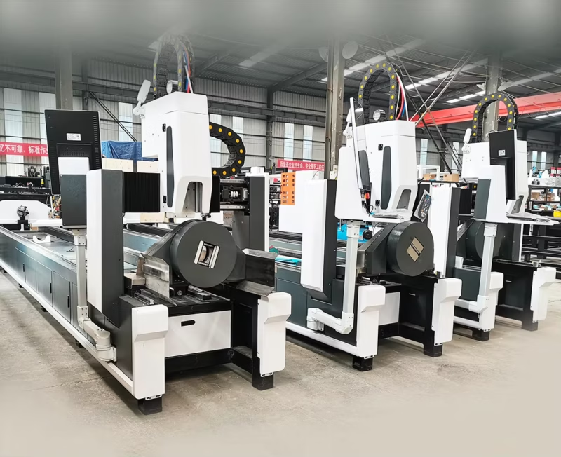
LT240S tube laser cutting machine
-
LT120S tube laser cutting machine
-
Sale

Tank Fillet Welding Machine
Original price was: $1,000.00.$900.00Current price is: $900.00. -
Sale

MAK100 tube laser cutting machine
Original price was: $5,500.00.$5,000.00Current price is: $5,000.00. -

portable plasma air cutting machine
$1,200.00 -

2in1 fiber laser cutting machine
-

Air cooling Laser welding machine
-

HF h beam laser cutting machine
-

LT240 laser cutting machine
-

Laser welding machine
-


Cobot Welding Station
-

Gantry welding robot solution
-

Tracked Wheeled AGV Welding robot
-

LFH6020 Fiber laser cutting machine
-
LFP6020
-

robotic welidng machine
Advanced Fiber Laser Tube Processing Technology
Our CNC Fiber Laser Tube Cutting systems revolutionize metal fabrication by integrating high-precision cutting, punching, and profiling into a single automated workflow. Designed for versatility, this technology handles a wide array of profiles including Round, Square, Rectangular, and Oval tubes, as well as complex L-shaped and U-shaped channels.
- Precision Punching: High-speed hole punching with micron-level accuracy, eliminating the need for mechanical drilling or die-stamping.
- Complex Profiling: Advanced 3D pathing allows for intricate interlocking joints and specialized notch cuts, ideal for structural frames.
- High Material Efficiency: Intelligent nesting software minimizes scrap, reducing raw material costs across large production runs.
- Clean Finish: Delivers oxide-free, burr-free edges that require zero secondary grinding before welding.

Seamlessly processing multiple profiles with consistent precision.
Global Delivery & Logistics


From our high-tech manufacturing facility directly to your global site. PCL WeldCut ensures secure packaging, professional handling, and reliable international logistics to safeguard your equipment throughout the entire journey.