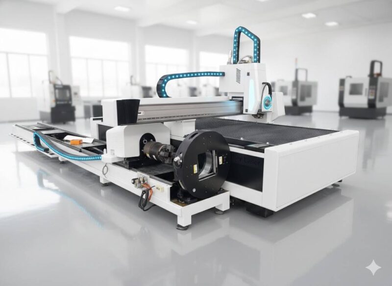
Advancing Pressure Vessel Fabrication through Fiber Laser Precision
The manufacturing of pressure vessels, including tanks, boilers, and heat exchangers, demands rigorous adherence to structural integrity and dimensional accuracy. Traditionally, these processes relied on manual layout and mechanical cutting, which introduced significant human error and material waste. The transition to fiber Laser Cutting has redefined the throughput capabilities of modern fabrication facilities. Unlike legacy thermal cutting methods, fiber lasers utilize a solid-state gain medium to generate a high-intensity beam capable of achieving extremely narrow kerf widths. This technical shift allows for the processing of carbon steel, stainless steel, and alloy plates with a precision that was previously unattainable in heavy-industrial applications.
The Role of 3D Vision Positioning in Large-Scale Components
One of the primary challenges in vessel fabrication is the inherent geometric deviation found in large-diameter cylinders and dished heads. Material rolling and forming processes often result in slight ellipticities or surface irregularities that traditional 2D cutting paths cannot account for. The integration of 3D vision positioning systems solves this by utilizing industrial cameras and laser scanners to generate a real-time point cloud of the workpiece.
Before the cutting cycle begins, the vision system performs a non-contact scan of the vessel component. The software compares the scanned data against the original CAD model, identifying discrepancies in curvature and position. The CNC controller then dynamically adjusts the cutting head’s path and height. This adaptive logic ensures that the focal point of the laser remains constant relative to the material surface, regardless of any physical deformation. This capability is critical for nozzle openings and manway cutouts where the intersection of two curved surfaces requires complex five-axis kinematics.
High-Precision Cutting: Eliminating Secondary Grinding
In high-pressure environments, the edge quality of a cutout is non-negotiable. Traditional mechanical or lower-density thermal cutting often leaves behind a significant heat-affected zone (HAZ) or dross, necessitating extensive manual grinding before assembly. Fiber laser cutting technology minimizes the HAZ due to its concentrated power density and high processing speeds. The resulting edges are clean, perpendicular, and characterized by low surface roughness.
By eliminating the grinding phase, an industrial engineer can significantly reduce the total cycle time per vessel. Furthermore, the absence of mechanical stress on the edge prevents micro-cracking, which is a common failure point during hydrostatic testing. The fiber laser’s ability to maintain a stable kerf even at high thicknesses ensures that the fit-up between the shell and the nozzles is airtight, reducing the volume of filler metal required in subsequent assembly steps.
Integrated Functionality: Punching, Marking, and Cutting
Efficiency in a lean manufacturing environment is measured by the reduction of material handling. Modern fiber laser systems for Pressure Vessels are designed as multi-process workcells. Rather than moving a 10-ton plate between different machines, the laser system executes a sequential workflow of marking, punching, and cutting in a single clamping operation.
Precision Hole Punching and Perforation
While the term “punching” in this context refers to the laser’s ability to pierce heavy plates with high-speed pulses, the result is functionally superior to mechanical punching. The laser can create high-aspect-ratio holes for small-diameter instrumentation ports with no taper. Because the process is non-contact, there is no tool wear, ensuring that the thousandth hole is as precise as the first. This is particularly beneficial for tube sheets where hundreds of identical penetrations are required.
Automated Part Marking for Traceability
Traceability is a core requirement of the ASME Boiler and Pressure Vessel Code (BPVC). Every component must be identifiable throughout its lifecycle. The fiber laser system utilizes a low-power setting to perform integrated part marking directly onto the metal surface. This includes heat numbers, serial numbers, and orientation lines for assembly. Because the marking is done in the same coordinate system as the cutting, the placement is perfect, ensuring that alignment marks for longitudinal seams are accurately positioned for the fit-up crew.
Kinematic Efficiency and Path Optimization
From an industrial engineering perspective, the optimization of the toolpath is essential for maximizing ROI. 3D vision allows for “nesting” on pre-formed surfaces. The algorithm calculates the most efficient route for the cutting head, minimizing “air-cut” time. In the context of pressure vessels, this often involves complex trajectories across the dome of a tank. The 5-axis fiber laser head, guided by vision data, maintains the optimal angle of incidence, preventing beam reflection and ensuring consistent energy absorption. This level of automation reduces the reliance on highly skilled manual operators, shifting the focus to system monitoring and quality assurance.
Economic Impact on Total Cycle Time
When analyzing the cost-benefit of fiber laser systems with 3D vision, the primary metric is the reduction in total cycle time. Traditional methods involve layout (2 hours), manual cutting (1 hour), and grinding/prep (2 hours). A fiber laser system with vision positioning can complete the same task in under 20 minutes, including setup. The reduction in labor costs is accompanied by a decrease in consumable usage—no grinding discs, no mechanical bits, and lower gas consumption compared to older technologies.
Furthermore, the precision of the fiber laser reduces the scrap rate. In the pressure vessel industry, where specialized alloys can cost thousands of dollars per ton, the ability to “measure twice and cut once” via automated vision scanning is a significant financial safeguard. The 3D vision system acts as an automated inspection gate, refusing to cut if the material is positioned outside of tolerance, thereby preventing the destruction of expensive workpieces.
Conclusion: The Future of Vessel Fabrication
The integration of fiber laser technology and 3D vision represents the pinnacle of current industrial fabrication. By focusing on high-precision output and the elimination of post-processing steps like grinding, manufacturers can achieve a level of operational excellence that meets the most stringent global standards. As pressure vessel designs become more complex and material costs fluctuate, the ability to automate the cutting, marking, and punching processes with absolute spatial awareness will remain the defining characteristic of a competitive manufacturing facility.
-


Cantilever Welding Robot solution
-


GF laser cutting machine
-

P3015 plasma cutting machine
-

LFP3015 Fiber Laser Cutter
-

pipe plasma cutting machine
-
LFH 4020 Fiber Laser Cutting Machine
-
LFP4020
-

gantry plasma air cutting machine
-

3D robot cutting machine
-

8 axis plasma cutting machine
-

5 axis plasma cutting machine
-

LT360 tube laser cutting machine
-

robot welding workstation
-

SF6060 fiber laser cutting machine
Advanced Fiber Laser Tube Processing Technology
Our CNC Fiber Laser Tube Cutting systems revolutionize metal fabrication by integrating high-precision cutting, punching, and profiling into a single automated workflow. Designed for versatility, this technology handles a wide array of profiles including Round, Square, Rectangular, and Oval tubes, as well as complex L-shaped and U-shaped channels.
- Precision Punching: High-speed hole punching with micron-level accuracy, eliminating the need for mechanical drilling or die-stamping.
- Complex Profiling: Advanced 3D pathing allows for intricate interlocking joints and specialized notch cuts, ideal for structural frames.
- High Material Efficiency: Intelligent nesting software minimizes scrap, reducing raw material costs across large production runs.
- Clean Finish: Delivers oxide-free, burr-free edges that require zero secondary grinding before welding.

Seamlessly processing multiple profiles with consistent precision.
Global Delivery & Logistics


From our high-tech manufacturing facility directly to your global site. PCL WeldCut ensures secure packaging, professional handling, and reliable international logistics to safeguard your equipment throughout the entire journey.