Precision Engineering in Oil and Gas Tank Fabrication
The production of pressure vessels and storage tanks for the oil and gas sector demands rigorous adherence to dimensional tolerances and material science standards. Traditional methods often struggle with the geometric complexities of ellipsoidal heads and large-diameter cylindrical shells. The introduction of Fiber Laser Cutting technology, enhanced by 3D vision systems, represents a fundamental shift in how heavy-gauge plate and dished components are processed. Unlike legacy mechanical methods, fiber laser systems utilize a concentrated, high-density energy source to achieve sublimation or melt-and-blow cutting with a kerf width often measuring less than 0.5mm.
Industrial engineers are increasingly prioritizing fiber laser systems due to their superior wall-plug efficiency and the absence of mechanical tool wear. In the context of oil and gas tanks, where materials like carbon steel and stainless steel are prevalent, the ability to maintain a consistent focal point across a non-linear surface is critical. The integration of 3D vision allows the machine to compensate for the inherent material deviations and “out-of-roundness” common in large-scale tank components.
The Role of 3D Vision Positioning Systems
Standard 2D laser cutting assumes a perfectly flat plane, which is rarely the case in tank manufacturing. 3D Vision positioning utilizes high-resolution cameras and laser sensors to perform a real-time spatial scan of the workpiece. This photogrammetry or structured light data is fed back into the CNC controller to generate a dynamic height and tilt compensation profile. When a laser head approaches a dished tank head, the vision system identifies the exact center and orientation of the component, adjusting the 5-axis or 6-axis motion path to remain perpendicular to the surface at all times.
This level of automation eliminates the manual setup errors associated with physical templates. The vision system can detect the edge of a plate or the curvature of a pre-formed dome within milliseconds. By mapping the actual topography of the metal, the software ensures that the cut geometry—whether it is a manhole opening or a nozzle interface—is dimensionally accurate relative to the tank’s actual physical state, rather than its theoretical CAD model.
Optimization of the Heat-Affected Zone
Material integrity is a primary concern in the Oil & Gas Tanks industry, where high-pressure environments can exploit any crystalline weakness in the metal. Fiber laser cutting is characterized by an extremely narrow heat-affected zone (HAZ). Because the energy is so localized and the cutting speed is significantly higher than alternative thermal processes, the surrounding material undergoes minimal thermal cycling.
From an engineering perspective, a reduced HAZ means the mechanical properties of the alloy—such as yield strength and corrosion resistance—remain largely unchanged near the cut edge. This is particularly vital for sour service tanks where localized hardening can lead to stress corrosion cracking. The high-velocity assist gas (typically oxygen or nitrogen) simultaneously cools the edge and expels molten material, resulting in a surface finish that often meets ISO 9013 Range 2 or 3 standards.
Elimination of Secondary Grinding Operations
One of the most significant cost-saving features of high-precision fiber laser cutting is the elimination of secondary grinding. Traditional thermal cutting often leaves a thick layer of dross or oxide that must be mechanically removed before subsequent assembly. Fiber lasers, however, produce a “clean-cut” edge. The slag-free quality of the cut means that components can move directly from the laser bed to the fit-up station.
In an industrial workflow, grinding is a labor-intensive, high-dust, and high-noise activity that creates a bottleneck. By utilizing a fiber laser with a high-power resonator (frequently 12kW to 30kW for tank applications), the edges are smooth enough for high-integrity fit-ups. This precision ensures that the gap between components is uniform, which is a prerequisite for automated assembly and consistent structural integrity in the final vessel.
Integrated Punching, Marking, and Cutting Logic
Modern fiber laser systems for tank fabrication are not merely cutting tools; they are multi-process workstations. The CNC logic allows for three distinct operations in a single program:
1. Marking: The laser can be de-focused or pulsed at low power to etch layout lines, heat numbers, or assembly instructions directly onto the tank surface. This ensures traceability without the stress concentrations caused by mechanical stamping.
2. Punching (Piercing): The system utilizes multi-stage piercing cycles, where the laser ramps up power and frequency to penetrate thick plates without creating “volcano” splashback. This protects the nozzle and ensures a clean start point for the cut.
3. Precision Cutting: Once the pierces and marks are complete, the machine executes the high-speed contour cutting. Because all three steps happen in a single setup, there is zero cumulative error from moving the workpiece between different machines.
Throughput and Operational Efficiency
From the standpoint of industrial engineering, the metrics of success are throughput and yield. Fiber lasers offer cutting speeds that are 3 to 5 times faster than older technology for mid-range thicknesses (6mm to 20mm). When combined with 3D vision that reduces setup time from hours to minutes, the overall Equipment Effectiveness (OEE) increases dramatically.
Furthermore, the software nesting capabilities for fiber lasers allow for tighter packing of parts on a single plate, reducing scrap rates. In the oil and gas industry, where high-grade alloys are expensive, a 5% increase in material utilization can translate to tens of thousands of dollars in annual savings. The lack of mechanical force applied to the plate during cutting also means that lighter, more flexible work-holding solutions can be used, further speeding up the loading and unloading cycles.
Conclusion on Technical Integration
The synergy between Fiber Laser Cutting and 3D vision systems provides a robust solution for the technical challenges of oil and gas tank manufacturing. By focusing on high-precision photon delivery and real-time geometric compensation, manufacturers can produce components that require no further mechanical dressing. The process preserves the metallurgical properties of the tank walls while providing a level of repeatability and speed that manual or 2D-restricted methods cannot match. For the industrial engineer, this represents the peak of modern fabrication efficiency—minimizing waste, labor, and time while maximizing structural reliability.
-


Cantilever Welding Robot solution
-


GF laser cutting machine
-

P3015 plasma cutting machine
-

LFP3015 Fiber Laser Cutter
-

pipe plasma cutting machine
-
LFH 4020 Fiber Laser Cutting Machine
-
LFP4020
-

gantry plasma air cutting machine
-

3D robot cutting machine
-

8 axis plasma cutting machine
-

5 axis plasma cutting machine
-

LT360 tube laser cutting machine
-

robot welding workstation
-

SF6060 fiber laser cutting machine
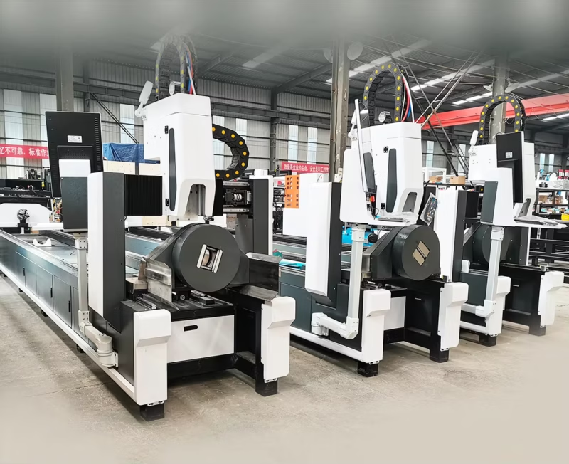
Advanced Fiber Laser Tube Processing Technology
Our CNC Fiber Laser Tube Cutting systems revolutionize metal fabrication by integrating high-precision cutting, punching, and profiling into a single automated workflow. Designed for versatility, this technology handles a wide array of profiles including Round, Square, Rectangular, and Oval tubes, as well as complex L-shaped and U-shaped channels.
- Precision Punching: High-speed hole punching with micron-level accuracy, eliminating the need for mechanical drilling or die-stamping.
- Complex Profiling: Advanced 3D pathing allows for intricate interlocking joints and specialized notch cuts, ideal for structural frames.
- High Material Efficiency: Intelligent nesting software minimizes scrap, reducing raw material costs across large production runs.
- Clean Finish: Delivers oxide-free, burr-free edges that require zero secondary grinding before welding.

Seamlessly processing multiple profiles with consistent precision.
Global Delivery & Logistics


From our high-tech manufacturing facility directly to your global site. PCL WeldCut ensures secure packaging, professional handling, and reliable international logistics to safeguard your equipment throughout the entire journey.