Optimizing LNG Infrastructure Fabrication with Fiber Laser Systems
The global demand for Liquefied Natural Gas (LNG) necessitates highly specialized infrastructure, including cryogenic storage tanks, regasification units, and intricate manifold systems. These components rely heavily on materials such as 304/304L stainless steel and 9% nickel steel, which demand extreme precision during the fabrication phase. Traditionally, material preparation involved multi-step processes including manual layout, mechanical punching, and abrasive cutting. The introduction of fiber Laser Cutting technology, enhanced by 3D vision positioning, has redefined these workflows by delivering micron-level accuracy and streamlined operations.
The Technical Advantage of 3D Vision Positioning
In large-scale LNG projects, raw materials such as large-diameter pipes or structural beams often exhibit slight deviations in geometry due to manufacturing tolerances or thermal deformation. Conventional fixed-coordinate laser cutting fails to account for these inconsistencies, leading to fit-up issues during assembly. 3D vision positioning utilizes high-resolution cameras and laser sensors to perform a real-time volumetric scan of the workpiece.
This system generates a digital twin of the physical material, allowing the CNC controller to adjust the cutting path dynamically. By calculating the exact spatial orientation and surface topography, the machine ensures that every aperture and contour is placed with absolute precision relative to the actual material geometry rather than a theoretical CAD model. This 3D vision positioning capability is critical for the complex nozzle intersections found in LNG piping modules.
Integrated Punching, Marking, and Cutting Sequences
Efficiency in industrial engineering is measured by the reduction of “touches” per part. Fiber laser systems designed for the LNG sector integrate three critical functions into a single program cycle:
Precision Punching (Perforation)
Instead of mechanical punching, which can induce stress cracks in hardened alloys, the fiber laser utilizes high-frequency pulsing to create pilot holes and fastener apertures. This thermal process ensures hole circularity and verticality, maintaining the structural integrity of the cryogenic vessel components.
Automated Marking and Traceability
LNG projects require stringent material traceability. The laser system can be tuned to a low-wattage marking mode, etching heat numbers, part IDs, and bend lines directly onto the material surface. Unlike ink-jet or physical stamping, laser marking is permanent and does not introduce contaminants into the material grain structure, which is vital for maintaining corrosion resistance in saline environments.
High-Speed Precision Cutting
The final stage involves the actual profile cutting. With power outputs ranging from 12kW to 30kW, fiber lasers can slice through thick-walled stainless steel with a narrow kerf width. The concentrated energy density results in a minimal Heat Affected Zone (HAZ), preserving the mechanical properties of the specialized alloys used in LNG service.
Eliminating Post-Processing: The No-Grinding Mandate
One of the most significant bottlenecks in traditional fabrication is the requirement for secondary grinding. Mechanical cutting or lower-quality thermal processes often leave dross, slag, or hardened edges. In the context of LNG projects, where weld quality is scrutinized via radiographic testing, any edge imperfection can lead to catastrophic failure or costly rework.
Fiber laser cutting produces a finished edge with a surface roughness (Ra) that often meets or exceeds the requirements for immediate assembly. Because the process uses an inert assist gas—typically nitrogen—to blow away molten material, the cut edge remains free of oxides. This “no grinding” capability allows fabricators to move parts directly from the laser bed to the assembly jig, significantly reducing labor costs and improving shop throughput.
Operational Impact on LNG Project Timelines
The implementation of a vision-guided fiber laser system addresses the critical path of LNG module construction. By automating the alignment process, the setup time for large-bore pipes or structural skids is reduced by up to 70%. Furthermore, the high cutting speeds of fiber lasers (frequently exceeding 20m/min on thinner gauges and maintaining stability on thick plates) ensure that fabrication schedules are insulated against delays.
From an engineering perspective, the reduction in scrap material is another quantifiable benefit. The precision of 3D scanning allows for tighter nesting of parts, even on irregular remnants. For expensive high-nickel alloys, a 5-10% improvement in material utilization can translate to hundreds of thousands of dollars in savings across a major LNG contract.
Enhancing Reliability in Cryogenic Applications
The reliability of LNG infrastructure is predicated on the quality of its individual components. High precision laser cutting ensures that every flange, support bracket, and manifold section fits with zero-clearance tolerances. This level of accuracy is essential for vacuum-insulated piping (VIP) and other specialized LNG equipment where thermal bridges must be minimized. The consistency of laser-cut parts also facilitates the use of orbital welding systems, which require uniform edge preparation to achieve high-integrity joints.
Future-Proofing Fabrication Facilities
As the LNG industry shifts toward modularization and prefabricated sub-assemblies, the role of the industrial engineer is to implement technologies that offer both flexibility and repeatability. Fiber laser machines equipped with 3D vision represent the pinnacle of this evolution. These systems are not merely cutting tools; they are integrated fabrication centers that handle material inspection, layout, and processing in a single automated environment.
By removing the variables associated with manual measurement and secondary cleaning, facilities can guarantee a level of quality that satisfies the stringent codes of the LNG sector (such as ASME B31.3 or EN 1473). The data generated by the 3D vision system can also be exported for Quality Assurance (QA) documentation, providing a digital record of the dimensional accuracy of every component produced.
Conclusion
In the competitive landscape of energy infrastructure, the transition to fiber laser cutting with 3D Vision positioning is a strategic necessity. By focusing on high-precision output, consolidating punch and mark operations, and strictly adhering to a “no-grinding” workflow, fabricators can achieve the throughput and quality levels required for the next generation of LNG projects. This technological shift optimizes the manufacturing floor, reduces lead times, and ensures the structural integrity of critical cryogenic systems.
-


Cantilever Welding Robot solution
-


GF laser cutting machine
-

P3015 plasma cutting machine
-

LFP3015 Fiber Laser Cutter
-

pipe plasma cutting machine
-
LFH 4020 Fiber Laser Cutting Machine
-
LFP4020
-

gantry plasma air cutting machine
-

3D robot cutting machine
-

8 axis plasma cutting machine
-

5 axis plasma cutting machine
-

LT360 tube laser cutting machine
-

robot welding workstation
-

SF6060 fiber laser cutting machine
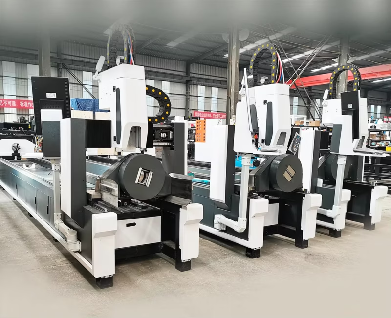
Advanced Fiber Laser Tube Processing Technology
Our CNC Fiber Laser Tube Cutting systems revolutionize metal fabrication by integrating high-precision cutting, punching, and profiling into a single automated workflow. Designed for versatility, this technology handles a wide array of profiles including Round, Square, Rectangular, and Oval tubes, as well as complex L-shaped and U-shaped channels.
- Precision Punching: High-speed hole punching with micron-level accuracy, eliminating the need for mechanical drilling or die-stamping.
- Complex Profiling: Advanced 3D pathing allows for intricate interlocking joints and specialized notch cuts, ideal for structural frames.
- High Material Efficiency: Intelligent nesting software minimizes scrap, reducing raw material costs across large production runs.
- Clean Finish: Delivers oxide-free, burr-free edges that require zero secondary grinding before welding.

Seamlessly processing multiple profiles with consistent precision.
Global Delivery & Logistics


From our high-tech manufacturing facility directly to your global site. PCL WeldCut ensures secure packaging, professional handling, and reliable international logistics to safeguard your equipment throughout the entire journey.