Precision Requirements in LNG Infrastructure Fabrication
The construction of Liquefied Natural Gas (LNG) facilities demands the highest levels of structural integrity and dimensional accuracy. Given that these systems operate under extreme cryogenic temperatures and high pressures, the materials used—primarily 9% nickel steel and various grades of austenitic stainless steel—require processing methods that minimize thermal stress and edge deformation. In the realm of industrial engineering, the transition toward Fiber Laser Cutting technology has become a baseline requirement for meeting these rigorous specifications.
Traditional fabrication workflows often suffer from cumulative tolerances, where small errors in initial cutting lead to significant alignment issues during assembly. For large-scale LNG projects, such as storage tank membranes, piping manifolds, and heat exchangers, the precision of the initial cut dictates the efficiency of the entire downstream process. High-power fiber lasers provide a concentrated energy source that achieves narrow kerf widths and minimal Heat Affected Zones (HAZ), which is critical for maintaining the fracture toughness of cryogenic alloys.
Integration of 3D Vision Positioning Systems
One of the most significant advancements in industrial cutting is the implementation of 3D vision positioning. In LNG projects, workpieces are often oversized or possess complex geometries that do not sit perfectly flat on a cutting bed. Traditional 2D cutting assumes a consistent Z-axis height and a perfectly aligned X-Y plane. However, real-world structural components often exhibit slight warping or deviation from the theoretical CAD model.
3D vision systems utilize high-speed industrial cameras and laser line scanners to create a real-time point cloud of the workpiece. The software compares this captured data against the original engineering design, automatically calculating offsets in six degrees of freedom. This ensures that the fiber laser head maintains a constant standoff distance and perpendicular orientation to the material surface, even if the material is bowed or slanted. For the engineer, this translates to “right-first-time” manufacturing, drastically reducing scrap rates in expensive nickel-alloy materials.
The Elimination of Secondary Grinding Operations
The primary bottleneck in conventional heavy fabrication is secondary processing. When edges are cut with low-precision methods, they require mechanical grinding to remove dross, slag, and carbonization before they can proceed to the assembly phase. In LNG applications, where oxygen cleanliness and surface finish are paramount, grinding is not only a labor-intensive cost center but also a potential source of contamination.
Modern LNG infrastructure fabrication utilizing high-wattage fiber lasers (ranging from 12kW to 30kW) produces an edge quality that is essentially “weld-ready.” The high-frequency beam oscillations and precise gas pressure control (using nitrogen or oxygen as assist gases) result in a mirror-like surface finish. By eliminating the grinding phase, facilities can realize a 30% to 50% reduction in total part processing time. This “no-grind” advantage is a cornerstone of Lean manufacturing, allowing for direct-to-fit assembly of complex piping spools and pressure vessel components.
Advanced Workflow: Punch, Mark, and Cut
Efficiency in industrial engineering is measured by the reduction of “touches” on a single workpiece. A fiber laser system integrated with 3D vision is not merely a cutting tool; it is a multi-functional processing center. The cryogenic material processing cycle can be programmed to perform three distinct operations in a single setup:
First, the system performs “punching” via high-speed piercing cycles. This is used for bolt holes or drainage ports with tolerances as tight as +/- 0.05mm. Second, the laser is used at a lower power setting for “marking.” This allows for the etching of part numbers, heat numbers, and alignment markers directly onto the steel. This ensures 100% traceability, which is a mandatory requirement for LNG safety audits and regulatory compliance. Finally, the system executes the high-power “cut” to finalize the geometry.
By consolidating these three steps, the risk of human error in layout and manual marking is removed. The 3D vision system ensures that the markings and holes are perfectly registered to the actual physical boundaries of the plate, regardless of how it was loaded onto the machine.
Metallurgical Integrity and Thermal Management
From a materials science perspective, the rapid cooling rate associated with fiber laser cutting is highly beneficial for the stainless steels used in LNG vaporization units. Because the laser moves at high velocities, the total heat input into the base metal is significantly lower than in other thermal processes. This prevents the precipitation of chromium carbides at the grain boundaries, a phenomenon known as sensitization, which could otherwise lead to intergranular corrosion in the demanding offshore environments where many LNG terminals are located.
The 3D vision system further enhances this by optimizing the cutting path to manage heat distribution. Smart nesting algorithms combined with vision-based thermal monitoring allow the machine to jump between different areas of the plate, preventing localized heat buildup that could lead to dimensional distortion. This is particularly important when processing thin-gauge 9% nickel steel membranes for LNG carriers, where even a few millimeters of thermal expansion can compromise the fit of the insulation system.
Operational Throughput and ROI Metrics
The Return on Investment (ROI) for a fiber laser system with 3D vision in an LNG context is driven by throughput and the reduction of manual labor. Industrial engineers focus on “arc-on time” or, in this case, “beam-on time.” Traditional methods involve significant downtime for setup, manual measurement, and edge cleanup. With automated 3D positioning, the setup time is reduced to the seconds it takes for the cameras to scan the bed.
Furthermore, the high beam quality of fiber lasers allows for faster feed rates on thick-section materials. For example, a 20mm stainless steel plate that previously required extensive processing can now be cut at speeds exceeding 2 meters per minute with a finish that requires no further refinement. When scaled across the thousands of components required for a mid-scale LNG liquefaction train, the time savings equate to months of shaved schedule from the project’s critical path.
Future-Proofing LNG Fabrication Facilities
As the global demand for natural gas continues to rise, the pressure on fabrication yards to deliver faster and more reliably will only increase. Integrating 3D vision with fiber laser technology is no longer an optional upgrade but a strategic necessity. It addresses the core engineering challenges of the LNG sector: material sensitivity, dimensional complexity, and the absolute requirement for safety and traceability.
By adopting a unified “punch-mark-cut” approach, engineers can ensure that every component—from the smallest bracket to the largest structural rib—is produced with a level of precision that matches the sophisticated nature of modern energy infrastructure. The elimination of secondary grinding and the optimization of material usage through vision-guided nesting represent the pinnacle of current industrial cutting capabilities.
-


Cantilever Welding Robot solution
-


GF laser cutting machine
-

P3015 plasma cutting machine
-

LFP3015 Fiber Laser Cutter
-

pipe plasma cutting machine
-
LFH 4020 Fiber Laser Cutting Machine
-
LFP4020
-

gantry plasma air cutting machine
-

3D robot cutting machine
-

8 axis plasma cutting machine
-

5 axis plasma cutting machine
-

LT360 tube laser cutting machine
-

robot welding workstation
-

SF6060 fiber laser cutting machine
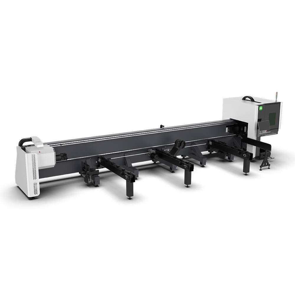
Advanced Fiber Laser Tube Processing Technology
Our CNC Fiber Laser Tube Cutting systems revolutionize metal fabrication by integrating high-precision cutting, punching, and profiling into a single automated workflow. Designed for versatility, this technology handles a wide array of profiles including Round, Square, Rectangular, and Oval tubes, as well as complex L-shaped and U-shaped channels.
- Precision Punching: High-speed hole punching with micron-level accuracy, eliminating the need for mechanical drilling or die-stamping.
- Complex Profiling: Advanced 3D pathing allows for intricate interlocking joints and specialized notch cuts, ideal for structural frames.
- High Material Efficiency: Intelligent nesting software minimizes scrap, reducing raw material costs across large production runs.
- Clean Finish: Delivers oxide-free, burr-free edges that require zero secondary grinding before welding.

Seamlessly processing multiple profiles with consistent precision.
Global Delivery & Logistics


From our high-tech manufacturing facility directly to your global site. PCL WeldCut ensures secure packaging, professional handling, and reliable international logistics to safeguard your equipment throughout the entire journey.