Advanced Fabrication in Construction Machinery via Fiber Laser Integration
The fabrication of heavy-duty construction machinery requires a rigorous adherence to structural integrity and dimensional accuracy. Traditionally, the industry relied on multi-step processes involving mechanical punching and thermal cutting, often followed by labor-intensive manual grinding to meet assembly specifications. The transition to a Fiber Laser Cutting Machine equipped with 3D Vision positioning represents a significant shift toward high-precision automated manufacturing. This technology addresses the inherent challenges of processing large-scale, high-strength steel plates used in the production of cranes, excavators, and mining equipment.
The Role of 3D Vision Positioning in Large-Format Cutting
In the context of heavy machinery, raw materials often exhibit slight deformations, surface irregularities, or positioning deviations when placed on a large-format cutting bed. 3D Vision Positioning utilizes industrial-grade cameras and laser displacement sensors to capture a three-dimensional point cloud of the workpiece. This data is processed through spatial transformation algorithms to align the digital cutting path with the physical orientation of the material.
Unlike standard 2D sensing, 3D vision accounts for the “tilt” and “warp” of heavy plates. By calculating the actual spatial coordinates of the plate’s surface, the system adjusts the laser head’s Z-axis height and the X-Y trajectory in real-time. This ensures that the focal point of the laser remains consistent across the entire work area, which is critical for maintaining kerf quality and preventing dross formation on the underside of the cut.
Eliminating Secondary Operations: The “No Grinding” Objective
A primary performance indicator for industrial engineers is the reduction of secondary processes. Conventional thermal cutting often leaves a thick oxide layer and a wide heat-affected zone (HAZ), necessitating grinding before the parts can move to assembly. A high-power fiber laser source, typically ranging from 12kW to 40kW for Construction Machinery, delivers energy with a wavelength of approximately 1.06 microns. This wavelength is highly absorbed by carbon steel, allowing for a concentrated energy density that vaporizes material instantly.
The result is a narrow kerf with a surface roughness (Ra) that often falls within the range of 6.3 to 12.5 microns, even on thick plates. Because the laser process minimizes the thermal input compared to older technologies, the edge remains metallurgical sound. This high-precision finish allows components to bypass the grinding station entirely, moving directly from the cutting bed to the next stage of the production line, thereby significantly reducing the total lead time.
Integrated Punching and Marking Capabilities
Modern Construction Machinery Fabrication demands more than just profile cutting. The integration of punching and marking within the laser cycle creates a “single-setup” manufacturing environment.
Precision Laser Punching
Laser “punching” or high-speed piercing is controlled through modulated pulse frequencies. For thick-section steel, the machine utilizes a multi-stage piercing strategy—starting with a low-frequency, high-peak-power pulse to create a pilot hole, followed by a continuous wave for the final penetration. This method prevents “cratering” and ensures that bolt holes are perfectly circular and perpendicular, meeting the tight tolerances required for mechanical fasteners in heavy equipment chassis.
Automated Marking for Traceability
Simultaneously, the fiber laser can be de-focused or run at lower power levels to perform marking. This is used for etching part numbers, batch codes, or alignment marks for subsequent assembly. By using the same tool head for marking as for cutting, there is zero offset error between the identification marks and the physical geometry of the part. This level of synchronization is vital for complex assemblies where hundreds of unique plates must be tracked through a digital twin system.
Technical Parameters and Kerf Precision
Achieving Kerf Precision in heavy plate processing requires meticulous control over the auxiliary gas dynamics and the beam profile. Nitrogen is often used for high-speed cutting of stainless components to prevent oxidation, while oxygen is typically utilized for carbon steel to facilitate an exothermic reaction that assists in the cutting speed. However, the 3D vision system plays a crucial role here by ensuring the nozzle-to-workpiece distance is maintained within a ±0.1mm tolerance.
From an engineering perspective, the fiber laser’s beam quality (measured as M²) is superior, allowing for a smaller spot size. This small spot size translates to a reduced kerf width, which not only saves material—allowing for tighter nesting of parts—but also enables the cutting of intricate internal geometries that would be impossible with mechanical tools. In the production of excavator buckets or boom arms, where weight reduction through optimized geometry is key, this precision is a fundamental requirement.
Managing Thermal Distortion through Intelligent Path Planning
Even with the efficiency of fiber lasers, heat accumulation in large plates can lead to thermal expansion, causing parts to shift during the cutting process. The 3D vision system provides a feedback loop that can detect these shifts mid-cycle. Furthermore, industrial engineers utilize the machine’s software to implement “bridge cutting” or “common-line cutting” strategies. By intelligently sequencing the cuts, the system distributes the thermal load across the plate, preventing the warping that would otherwise compromise the dimensional accuracy of long structural members.
Economic and Operational Impact
The implementation of a fiber laser system with 3D vision positioning transforms the economics of the workshop floor. The primary savings are realized through:
- Material Utilization: High nesting efficiency due to narrow kerf widths.
- Labor Reduction: Eliminating the need for manual grinding and separate marking/punching stations.
- Energy Efficiency: Fiber lasers typically have a wall-plug efficiency of 30-40%, significantly higher than CO2 alternatives.
- Maintenance: The solid-state nature of fiber lasers removes the need for complex internal optics and gas-flow turbines, leading to higher uptime in 24/7 construction machinery production environments.
Conclusion on Industrial Engineering Implementation
For the construction machinery industry, the shift toward integrated 3D-vision-guided fiber laser cutting is not merely an upgrade in speed; it is a fundamental shift in quality control. By consolidating punching, marking, and high-precision cutting into a single automated process, manufacturers eliminate the inconsistencies associated with manual labor and multi-machine setups. The ability to produce “weld-ready” parts straight from the cutting table, with no requirement for grinding and with absolute confidence in spatial positioning, provides a decisive competitive advantage in the global heavy equipment market.
-


LT240S tube laser cutting machine
-
LT120S tube laser cutting machine
-
Sale

Tank Fillet Welding Machine
Original price was: $1,000.00.$900.00Current price is: $900.00. -
Sale

MAK100 tube laser cutting machine
Original price was: $5,500.00.$5,000.00Current price is: $5,000.00. -

portable plasma air cutting machine
$1,200.00 -

2in1 fiber laser cutting machine
-

Air cooling Laser welding machine
-

HF h beam laser cutting machine
-

LT240 laser cutting machine
-

Laser welding machine
-


Cobot Welding Station
-

Gantry welding robot solution
-

Tracked Wheeled AGV Welding robot
-

LFH6020 Fiber laser cutting machine
-
LFP6020
-

robotic welidng machine
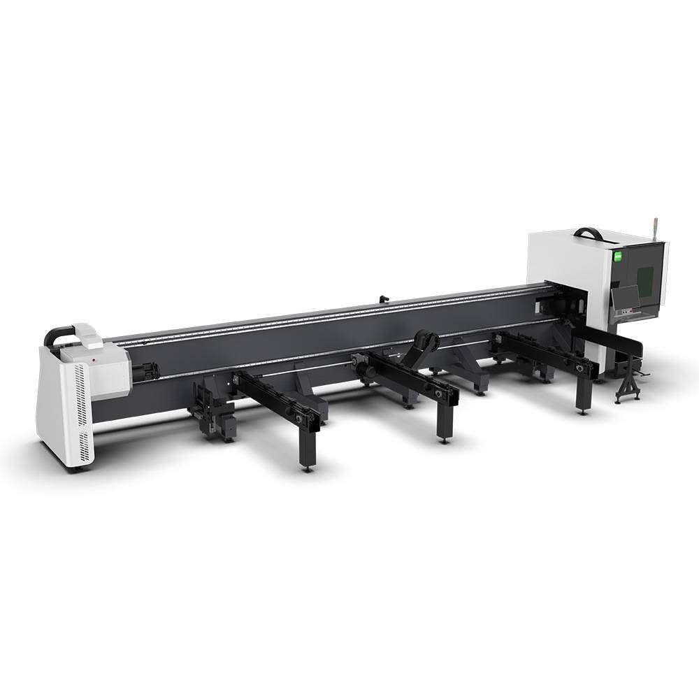
Advanced Fiber Laser Tube Processing Technology
Our CNC Fiber Laser Tube Cutting systems revolutionize metal fabrication by integrating high-precision cutting, punching, and profiling into a single automated workflow. Designed for versatility, this technology handles a wide array of profiles including Round, Square, Rectangular, and Oval tubes, as well as complex L-shaped and U-shaped channels.
- Precision Punching: High-speed hole punching with micron-level accuracy, eliminating the need for mechanical drilling or die-stamping.
- Complex Profiling: Advanced 3D pathing allows for intricate interlocking joints and specialized notch cuts, ideal for structural frames.
- High Material Efficiency: Intelligent nesting software minimizes scrap, reducing raw material costs across large production runs.
- Clean Finish: Delivers oxide-free, burr-free edges that require zero secondary grinding before welding.

Seamlessly processing multiple profiles with consistent precision.
Global Delivery & Logistics


From our high-tech manufacturing facility directly to your global site. PCL WeldCut ensures secure packaging, professional handling, and reliable international logistics to safeguard your equipment throughout the entire journey.