Field Technical Report: Deployment of Water-Cooled Automated MAG Welding Cell
Project Overview: Site 442 – Michigan, USA
This report details the operational integration and performance analysis of the newly commissioned Automated MAG Welding Cell at our heavy fabrication facility in Michigan. The objective was to replace manual GMAW (Gas Metal Arc Welding) processes for high-volume Structural Steel welding with a precision-controlled robotic system. Given the regional climate—specifically the high humidity fluctuations in the Great Lakes area—and the high-duty cycle requirements of 1-inch thick A36 plate, the implementation of advanced Arc Welding Solutions was paramount to maintaining metallurgical integrity and throughput.
The transition from manual to automated systems was driven by a 40% backlog in structural assembly. The following sections outline the technical configurations, the synergy between the hardware and the arc logic, and the critical lessons learned during the first 500 hours of operation.
1. Technical Configuration of the Automated MAG Welding Cell
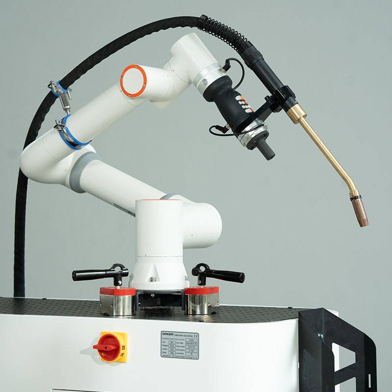
The cell consists of a six-axis industrial robot integrated with a 500-ampere inverter power source and a heavy-duty water-cooled torch. In the context of Michigan’s industrial environment, thermal management is not merely a preference but a requirement for 100% duty cycle operations. We opted for a closed-loop water-cooling system to mitigate the heat soak common in high-amperage Structural Steel welding.
1.1. Water-Cooling and Thermal Stability
During initial trials using air-cooled torches, we observed significant contact tip recession and erratic wire feeding after 15 minutes of continuous arc-on time. The heat generated when welding heavy-gauge structural sections (fillets exceeding 12mm) led to thermal expansion of the copper internals. By switching to a water-cooled Automated MAG Welding Cell, we stabilized the internal diameter of the contact tip. This maintained a consistent “Electrical Stick-Out” (ESO), which is critical for the “Arc Welding Solutions” software to accurately calculate voltage offsets in real-time.
1.2. Michigan Environmental Considerations
The Michigan facility experiences significant temperature swings. During the winter months, condensation in the gas lines became an issue. We implemented an inline gas heater and a secondary filtration system to ensure the 80/20 Ar-CO2 mix remained dry. Moisture in the MAG process leads to hydrogen-induced cracking, a fatal flaw in Structural Steel welding. The automated cell’s sensors were calibrated to halt operation if the ambient dew point crossed a specific threshold, protecting the weld pool from porosity.
2. Synergizing Arc Welding Solutions with Automated Systems
The term “Arc Welding Solutions” refers to the suite of waveform controls and adaptive feedback loops that govern the Automated MAG Welding Cell. In this deployment, the synergy between the robot’s motion and the power source’s pulse-logic was the deciding factor in project success.
2.1. Adaptive Arc Logic
Structural steel is rarely perfectly uniform. Variations in fit-up—specifically gaps ranging from 0.5mm to 2.5mm—required an adaptive arc solution. We utilized “Through-Arc Seam Tracking” (TAST). As the robot weaves across the joint, the system monitors the current. If the current spikes, the arc is too close; if it drops, the gap has widened. The Arc Welding Solutions integrated into this cell allow the robot to adjust its path and travel speed dynamically, ensuring full penetration without manual intervention.
2.2. Pulse-on-Pulse Regimes
To reduce post-weld cleanup (spatter), we programmed the Automated MAG Welding Cell with a modified spray transfer mode. By pulsing the current, we achieved “one drop per pulse” metal transfer. This is essential for Structural Steel welding where aesthetics and clean-up time directly impact the bottom line. In our Michigan trials, we reduced spatter-related downtime by 85% compared to the previous manual GMAW stations.
3. Structural Steel Welding: Material Challenges
The primary material processed at this site is ASTM A36 and A572 Grade 50. These steels are prone to distortion if the heat input is not strictly controlled. The Automated MAG Welding Cell provides a level of heat-input consistency that is humanly impossible over an 8-hour shift.
3.1. Heat Input Management
Excessive heat input in Structural Steel welding enlarges the Heat Affected Zone (HAZ), potentially reducing the yield strength of the member. Our Arc Welding Solutions included a “Cold Pulse” program for the root passes of thick-walled H-beams. This allowed for high deposition rates while maintaining a cooler overall weld pool, preventing burn-through on the web-to-flange transitions.
3.2. Wire Selection and Feedability
We standardized on a 1.2mm ER70S-6 wire. Given the length of the conduits in a robotic Automated MAG Welding Cell, we encountered “bird-nesting” early in the deployment. The solution was the installation of a four-roll drive system with serrated rollers and a high-torque motor. This ensured that even during complex 6-axis maneuvers, the wire delivery to the Structural Steel welding joint remained constant.
4. Lessons Learned and Field Corrections
Engineering success is often built on the failures identified during the commissioning phase. The Michigan site provided several key insights that will be applied to future Arc Welding Solutions deployments.
4.1. The “Grounding” Trap
In the first week, we noticed intermittent arc instability. The Automated MAG Welding Cell was grounded to the cell frame, but the heavy structural workpieces were not consistently making contact due to mill scale. Lesson: We implemented a dedicated rotary grounding clamp directly onto the workpiece positioner. In Structural Steel welding, you cannot rely on gravity for a consistent electrical return path. Once the ground was modernized, the arc wandering issues vanished.
4.2. Maintenance of Water-Cooling Lines
We initially used standard tap water for the cooling system. Within three months, Michigan’s hard water caused mineral buildup in the torch neck, leading to a flow restriction and a blown torch head. Lesson: All Automated MAG Welding Cells must use a deionized water/glycol mix. We also added a flow-rate sensor that triggers an E-stop if the liters-per-minute (LPM) drop below 1.5. This protects the $3,000 torch investment from catastrophic failure.
4.3. Sensor Drift in High-EMF Environments
The electromagnetic field (EMF) generated by 500A welding can interfere with the robot’s encoders and the Arc Welding Solutions feedback sensors. We had to replace standard shielded cables with high-density braided shielding and ensure that signal cables were routed at 90-degree angles to power cables. This eliminated “ghost” errors in the robot’s positioning during long-seam Structural Steel welding.
5. Economic and Quality Impact
The deployment of the Automated MAG Welding Cell in the Michigan plant has resulted in a 22% reduction in filler metal waste and a 35% increase in “Arc-On” time. More importantly, the ultrasonic testing (UT) failure rate on critical structural junctions dropped from 4% (manual) to 0.2% (automated).
The Arc Welding Solutions implemented—specifically the adaptive seam tracking and the pulsed-spray transfer—have allowed us to employ operators as “cell technicians” rather than just “welders.” This shift in labor utilization is critical for the Michigan manufacturing landscape, where skilled manual welders are increasingly difficult to recruit.
6. Final Technical Summary
The successful integration of this Automated MAG Welding Cell demonstrates that high-amperage Structural Steel welding can be effectively managed through a combination of robust hardware and intelligent Arc Welding Solutions. The water-cooled torch configuration proved essential for the heavy-duty cycles required in this Michigan facility. Moving forward, the site will implement a predictive maintenance schedule for the cooling system and gas delivery units to ensure the longevity of the cell. The data gathered here serves as a benchmark for the upcoming Phase 2 expansion.
Report Prepared By: Senior Welding Engineer, Site 442.
Status: Operational / Optimized.
-


Cantilever Welding Robot solution
-


GF laser cutting machine
-

P3015 plasma cutting machine
-

LFP3015 Fiber Laser Cutter
-

pipe plasma cutting machine
-
LFH 4020 Fiber Laser Cutting Machine
-
LFP4020
-

gantry plasma air cutting machine
-

3D robot cutting machine
-

8 axis plasma cutting machine
-

5 axis plasma cutting machine
-

LT360 tube laser cutting machine
-

robot welding workstation
-

SF6060 fiber laser cutting machine
Advanced Fiber Laser Tube Processing Technology
Our CNC Fiber Laser Tube Cutting systems revolutionize metal fabrication by integrating high-precision cutting, punching, and profiling into a single automated workflow. Designed for versatility, this technology handles a wide array of profiles including Round, Square, Rectangular, and Oval tubes, as well as complex L-shaped and U-shaped channels.
- Precision Punching: High-speed hole punching with micron-level accuracy, eliminating the need for mechanical drilling or die-stamping.
- Complex Profiling: Advanced 3D pathing allows for intricate interlocking joints and specialized notch cuts, ideal for structural frames.
- High Material Efficiency: Intelligent nesting software minimizes scrap, reducing raw material costs across large production runs.
- Clean Finish: Delivers oxide-free, burr-free edges that require zero secondary grinding before welding.

Seamlessly processing multiple profiles with consistent precision.
Global Delivery & Logistics


From our high-tech manufacturing facility directly to your global site. PCL WeldCut ensures secure packaging, professional handling, and reliable international logistics to safeguard your equipment throughout the entire journey.