Field Report: Robotic MIG/MAG Integration for Heavy Infrastructure – Casablanca Industrial Zone
1.0 Introduction and Site Context
This report details the deployment and optimization of a Single Pulse MIG/MAG Welding Robot at a heavy fabrication facility in the Aïn Sebaâ industrial district of Casablanca, Morocco. The project objective was to transition manual welding processes for structural sub-assemblies to an automated system capable of handling Thick Plate Steel welding (15mm to 40mm thickness).
Operating in Casablanca presents specific environmental challenges. The proximity to the Atlantic coast introduces high ambient humidity, which directly impacts the storage of consumables and the stability of the arc. Furthermore, the local power grid in the industrial zone showed voltage fluctuations of ±8%, necessitating the integration of advanced Arc Welding Solutions with robust power compensation capabilities to maintain weld integrity.
2.0 System Synergy: The MIG/MAG Welding Robot and Integrated Solutions
The core of the installation is a 6-axis industrial MIG/MAG Welding Robot coupled with a 500A high-duty cycle power source. However, a robot is merely a motion controller; its success in a heavy-duty environment depends entirely on the “Arc Welding Solutions” surrounding it. This includes the torch cleaning station, the wire drive system, and the synergic software governing the pulse parameters.
2.1 Hardware Configuration
We selected a water-cooled torch configuration to handle the high radiant heat generated during multi-pass Thick Plate Steel welding. In Casablanca’s mid-day heat, air-cooled torches frequently hit duty-cycle limits, leading to contact tip expansion and “burn-back” issues. By integrating a dedicated cooling unit into our Arc Welding Solutions package, we maintained a constant temperature at the contact tip, ensuring a stable CTWD (Contact-to-Work Distance).
2.2 Software and Synergic Logic
The MIG/MAG Welding Robot was programmed using synergic lines specifically tuned for M21 gas mixtures (82% Argon / 18% CO2), which are standard in the Moroccan market. The single-pulse regime was chosen over standard spray transfer to reduce spatter and improve the wetting of the toes of the weld on S355JR grade steel.
3.0 Technical Deep-Dive: Thick Plate Steel Welding Challenges
Welding thick sections (above 20mm) requires more than just high amperage. It requires meticulous thermal management and joint geometry control. In this field application, we were dealing with double-V butt joints and heavy fillet welds for crane girder supports.
3.1 Root Pass Penetration
The primary hurdle in Thick Plate Steel welding is achieving consistent root penetration without burn-through. We utilized the MIG/MAG Welding Robot’s “Touch-Sense” capability to find the work-piece position before every arc-start. Due to the thermal warping of thick plates during tacking, the physical joint path often deviated from the CAD model by up to 3mm. The sensing logic allowed the Arc Welding Solutions to adjust the tool center point (TCP) in real-time.
3.2 Multi-Pass Strategy and Interpass Temperature
For a 25mm V-groove, we implemented a 12-pass sequence. A common mistake in robotic implementation is ignoring interpass temperature. If the plate exceeds 250°C, the cooling rate slows down, potentially leading to a coarse grain structure and reduced impact toughness. We integrated an infrared pyrometer into the robot’s logic; the MIG/MAG Welding Robot was programmed to “dwell” if the sensor detected temperatures above our specified limit, ensuring the metallurgical integrity of the Thick Plate Steel welding.
4.0 Optimizing the Single Pulse Parameters
The single-pulse waveform was fine-tuned to balance “arc force” and “puddle fluidity.” In Casablanca, we found that the local Ar/CO2 mix varied slightly in purity between batches. This required us to adjust the pulse frequency (Hz) and peak current (Ip) to maintain a “one drop per pulse” metal transfer.
4.1 Arc Stability and Spatter Reduction
By utilizing advanced Arc Welding Solutions, we reduced post-weld cleaning time by 85%. Manual welding on these thick plates usually resulted in significant “shot-blast” time due to spatter. The pulsed MIG/MAG Welding Robot creates a controlled droplet transfer, which is essential when the torch is oscillating in a deep groove. We set the peak current high enough to pinch the droplet off effectively but maintained a base current sufficient to keep the ionized path (the arc) from extinguishing.
5.0 Lessons Learned from the Field
Engineering in a North African industrial context provides unique data points that are often missed in controlled lab environments. Below are the three critical “lessons learned” during this deployment.
5.1 Consumable Management in Humid Climates
Casablanca’s humidity is a silent killer for weld quality. We initially observed porosity in the thick plate root passes. Investigation revealed that the wire spools, if left on the MIG/MAG Welding Robot overnight, were picking up surface moisture.
Lesson: We implemented heated wire-dispensing drums and insisted on vacuum-sealed storage. Once the wire was protected, the hydrogen-induced cracking risks in our Thick Plate Steel welding dropped to near zero.
5.2 The Necessity of Seam Tracking
In Thick Plate Steel welding, the sheer mass of the parts means that “perfect” fit-up is a myth. Our initial trials without “Arc Data Monitoring” (Through-Arc Seam Tracking or TAST) failed because the robot stayed on its programmed path while the plate expanded and moved 4mm due to heat.
Lesson: Effective Arc Welding Solutions must include TAST for plates over 12mm. The MIG/MAG Welding Robot must “listen” to the arc’s electrical characteristics to shift its path laterally and vertically during the weave.
5.3 Earth Grounding and High-Frequency Interference
The workshop in Casablanca shared a ground with several large CNC plasma cutters. We experienced “arc wandering” where the robot’s arc would physically deflect toward the gantry.
Lesson: For robotic MIG/MAG Welding Robot setups, a dedicated, isolated earth ground is non-negotiable. We drove a 3-meter copper rod specifically for the robot cell, which stabilized the arc plasma column and improved the consistency of the Thick Plate Steel welding beads.
6.0 Productivity and Quality Results
After three weeks of optimization, the results were quantified against the previous manual baseline:
- Deposition Rate: Increased from 3.2 kg/hr (manual) to 6.5 kg/hr (robotic) using 1.2mm ER70S-6 wire.
- Repair Rate: Ultrasonic Testing (UT) failure rate dropped from 12% to less than 1.5% on Thick Plate Steel welding joints.
- Gas Consumption: Reduced by 20% due to the optimized pre-flow and post-flow settings managed by the Arc Welding Solutions software.
7.0 Conclusion
The successful integration of the MIG/MAG Welding Robot in Casablanca proves that automation is viable for heavy Moroccan industry, provided the environmental and metallurgical variables are controlled. The synergy between the robot’s precision and the “Arc Welding Solutions” (pulse control, seam tracking, and thermal monitoring) allowed us to master Thick Plate Steel welding in a way that manual labor simply cannot replicate for 10-hour shifts. The focus now shifts to training local technicians on waveform adjustment to ensure long-term autonomy of the cell.
End of Report.
Prepared by: Senior Welding Engineer
Location: Casablanca, Morocco
-


LT240S tube laser cutting machine
-
LT120S tube laser cutting machine
-
Sale

Tank Fillet Welding Machine
Original price was: $1,000.00.$900.00Current price is: $900.00. -
Sale

MAK100 tube laser cutting machine
Original price was: $5,500.00.$5,000.00Current price is: $5,000.00. -

portable plasma air cutting machine
$1,200.00 -

2in1 fiber laser cutting machine
-

Air cooling Laser welding machine
-

HF h beam laser cutting machine
-

LT240 laser cutting machine
-

Laser welding machine
-


Cobot Welding Station
-

Gantry welding robot solution
-

Tracked Wheeled AGV Welding robot
-

LFH6020 Fiber laser cutting machine
-
LFP6020
-

robotic welidng machine
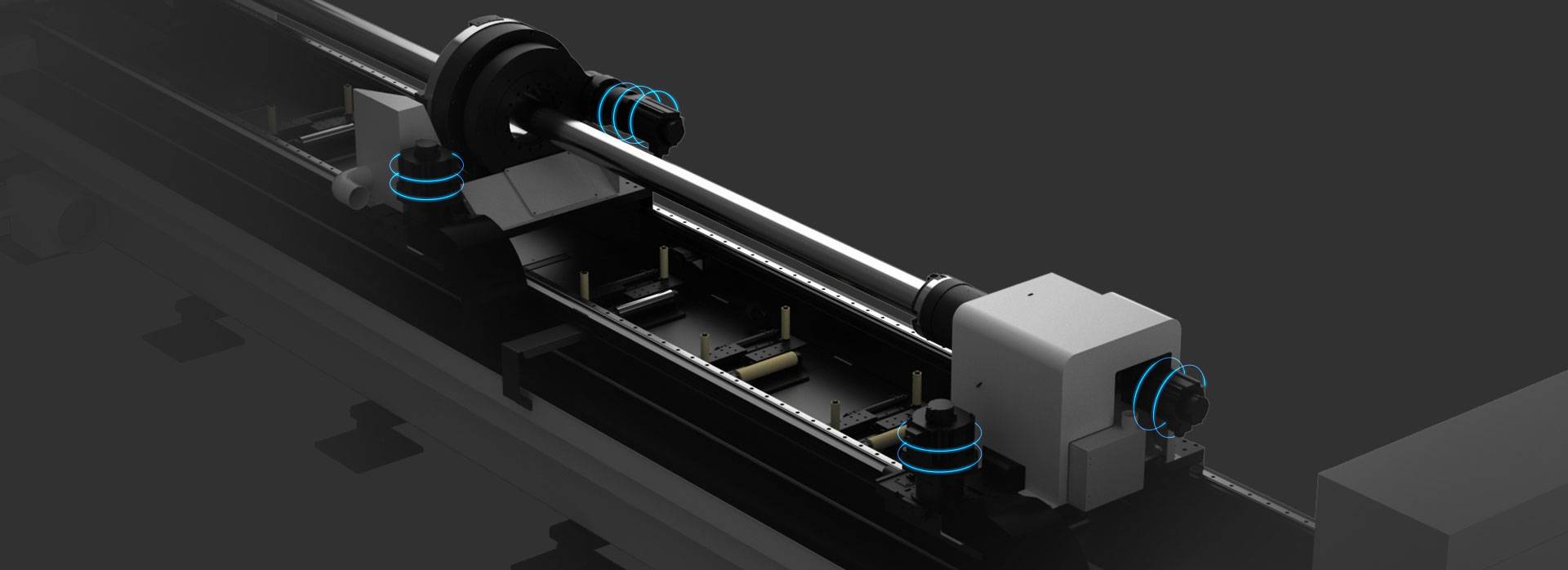
Advanced Fiber Laser Tube Processing Technology
Our CNC Fiber Laser Tube Cutting systems revolutionize metal fabrication by integrating high-precision cutting, punching, and profiling into a single automated workflow. Designed for versatility, this technology handles a wide array of profiles including Round, Square, Rectangular, and Oval tubes, as well as complex L-shaped and U-shaped channels.
- Precision Punching: High-speed hole punching with micron-level accuracy, eliminating the need for mechanical drilling or die-stamping.
- Complex Profiling: Advanced 3D pathing allows for intricate interlocking joints and specialized notch cuts, ideal for structural frames.
- High Material Efficiency: Intelligent nesting software minimizes scrap, reducing raw material costs across large production runs.
- Clean Finish: Delivers oxide-free, burr-free edges that require zero secondary grinding before welding.

Seamlessly processing multiple profiles with consistent precision.
Global Delivery & Logistics



From our high-tech manufacturing facility directly to your global site. PCL WeldCut ensures secure packaging, professional handling, and reliable international logistics to safeguard your equipment throughout the entire journey.