Field Engineering Report: Single Pulse MAG Cobot Implementation for Marine-Grade Aluminum Fabrication
1. Project Scope and Site Overview
This report documents the field deployment of a Single Pulse MAG Cobot Welder system at a medium-scale fabrication facility in the Tuas Industrial Estate, Singapore. The primary objective was the transition from manual GTAW (TIG) to semi-automated GMAW (MAG) processes for high-volume Aluminum Alloy welding, specifically 5083 and 6061 grades used in marine battery housings and offshore structures.
The Singaporean context presents unique challenges: limited floor space, a chronic shortage of highly skilled manual welders, and high ambient humidity levels (often exceeding 80%) which complicates aluminum metallurgy. By integrating advanced Arc Welding Solutions with collaborative robotics, we aimed to stabilize weld quality while reducing the dependence on specialized 6G-certified manual operators.
2. Integration Synergy: MAG Cobot Welder and Arc Welding Solutions
The success of this deployment rested on the synergy between the hardware—the MAG Cobot Welder—and the software-driven Arc Welding Solutions. In a traditional robotic cell, the barrier to entry is the complex programming and fixed guarding. In the Singapore workshop environment, where batch sizes vary, the cobot’s “lead-through” programming is the differentiator.
2.1. The Pulse Control Logic
Standard MAG welding on aluminum often results in excessive spatter and burn-through on thinner gauges. The “Single Pulse” function within our Arc Welding Solutions package allows for a one-drop-per-pulse metal transfer. This is critical for Aluminum Alloy welding because it provides the cleaning action (removing the oxide layer) without the massive heat input of a spray transfer. During the Tuas field trials, we calibrated the pulse frequency to match the cobot’s travel speed, ensuring that the “ripple” effect mirrored high-quality manual TIG, but at three times the deposition rate.
2.2. Collaborative Dynamics
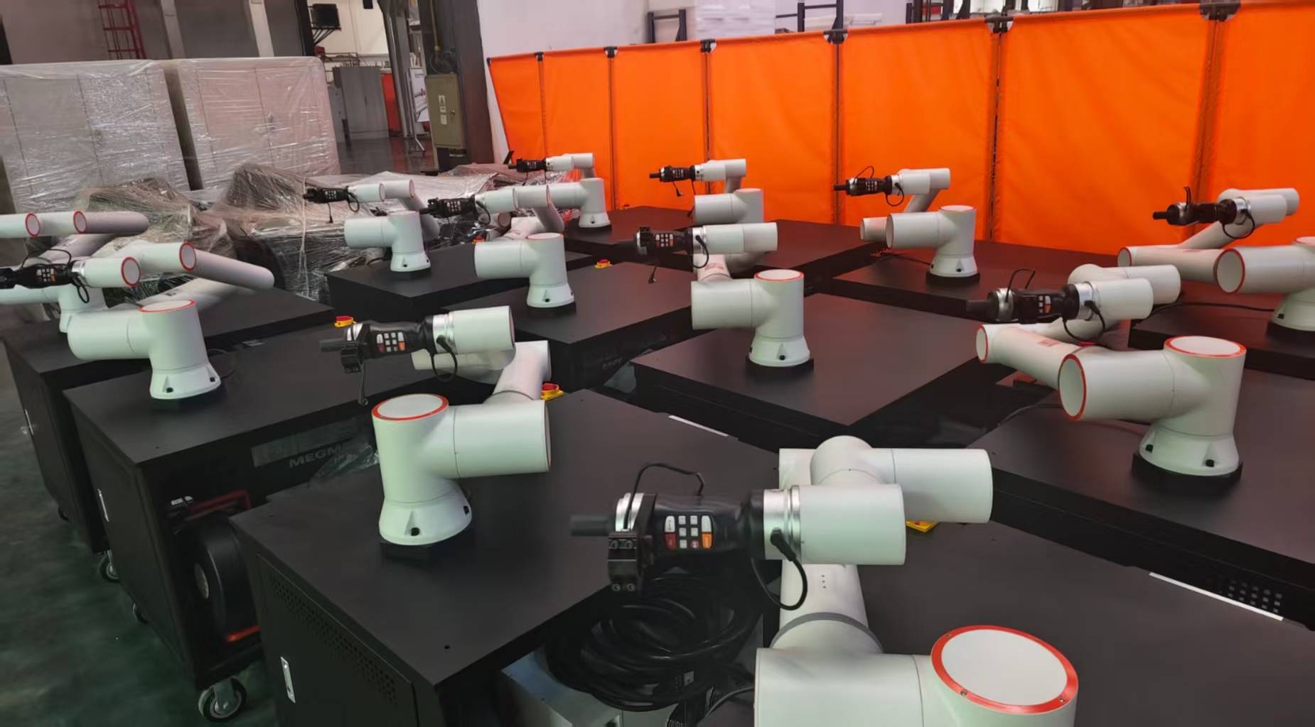
The MAG Cobot Welder was integrated with a 400A pulse power source. Unlike traditional industrial robots, the cobot allowed our existing fabricators to work alongside the machine, performing tack welding and fit-up on one side of the jig while the cobot executed the long seams on the other. This parallel workflow effectively halved the lead time for marine-grade enclosures.
3. Technical Analysis: Aluminum Alloy Welding Performance
Welding 5xxx and 6xxx series aluminum requires a deep understanding of thermal conductivity. Aluminum dissipates heat nearly five times faster than steel, which usually necessitates high current. However, high current leads to distortion. This is where the MAG Cobot Welder proves its worth.
3.1. Porosity and Humidity Management
In the Singapore environment, hydrogen porosity is a constant threat. We observed that the consistency of the cobot’s torch angle (fixed at 15 degrees push) significantly improved shielding gas coverage compared to manual operators who tended to vary their angle as they fatigued. We utilized a 1.2mm ER5356 wire with a high-purity Argon-Helium mix (Ar-He 30%). The helium addition increased the arc temperature at the puddle, allowing the MAG Cobot Welder to achieve full penetration on 6mm plates without the need for extensive pre-heating.
3.2. Bead Profile and Heat Affected Zone (HAZ)
Using the single pulse settings, we monitored the HAZ in the 6061-T6 samples. Excessive heat typically degrades the mechanical properties of T6 aluminum. The Arc Welding Solutions utilized in this project featured a “Synchro-Pulse” mode, which alternates between two different energy levels. This provided exceptional control over the weld pool, resulting in a narrower HAZ and a tensile strength retention of roughly 85% of the base metal, which is well within marine certification standards.
4. Practical Field Observations and Lessons Learned
The transition from a manual shop to a cobot-assisted shop is not purely a “plug-and-play” affair. Several technical hurdles were identified during the first 30 days of operation in Singapore.
4.1. Wire Feeding Constraints
Aluminum wire is soft and prone to “bird-nesting.” We found that even with the MAG Cobot Welder, the length of the torch cable was a critical factor. We shortened the umbilical to 3 meters and switched to Teflon liners with “U-groove” rollers. In the high-humidity Singapore climate, we also had to implement heated wire storage cabinets. Leaving a spool on the cobot overnight resulted in moisture condensation on the wire surface, leading to arc instability the following morning.
4.2. Workpiece Grounding (The “Silent” Failure)
A recurring issue in the first week was arc wandering. We traced this back to inconsistent grounding on the rotating welding table. For Aluminum Alloy welding, the high frequency of the pulse arc is sensitive to changes in resistance. We solved this by installing a dual-grounding strap system directly to the jig, bypassing the table bearings. This stabilized the Arc Welding Solutions feedback loop, ensuring the voltage remained constant within +/- 0.5V.
4.3. TCP Calibration and Path Accuracy
The Tool Center Point (TCP) must be calibrated daily. In the Tuas facility, temperature swings between the non-air-conditioned shop floor (34°C) and the localized cooling fans caused minor thermal expansion in the aluminum jigs. We taught the operators to run a “dry run” check on the first part of every shift to ensure the MAG Cobot Welder was tracking the root of the joint accurately. A deviation of even 1mm on a fillet weld can lead to lack of fusion on the vertical member.
5. Economic and Productivity Metrics
Before the implementation of the MAG Cobot Welder, the rejection rate for X-ray quality aluminum welds was approximately 12% due to human error (mostly stop-start defects). After 500 units, the rejection rate dropped to less than 2%.
- Deposition Rate: Increased from 1.2 kg/hr (Manual TIG) to 3.8 kg/hr (Pulse MAG Cobot).
- Gas Consumption: Reduced by 15% due to optimized pre-flow and post-flow settings in the Arc Welding Solutions software.
- Labor Allocation: One skilled welder now supervises three cobot stations, significantly alleviating the labor pressure in the Singapore market.
6. Safety and Collaborative Environment
A major concern for the Singapore Ministry of Manpower (MOM) is the safety of automated systems. The MAG Cobot Welder utilized force-torque sensors that stop motion upon a 50N collision. This allowed us to remove the heavy safety fencing, reclaiming approximately 12 square meters of floor space. We did, however, implement specialized localized exhaust ventilation (LEV) to handle the increased fume production associated with the higher deposition rates of Aluminum Alloy welding.
7. Final Technical Recommendations
For engineering firms in Singapore looking to adopt similar Arc Welding Solutions, I recommend the following:
- Standardize Jigs: The cobot is only as good as the fit-up. Use toggle clamps and precision-machined aluminum or stainless-steel jigs to prevent heat-sink variations.
- Invest in Waveform Editing: Don’t rely on factory presets. Fine-tune the “Peak Current” and “Base Current” to find the sweet spot for your specific Aluminum Alloy welding grade.
- Environmental Control: While a full cleanroom isn’t necessary, the welding area should be shielded from drafts (to prevent gas turbulence) and humidity should be monitored.
8. Concluding Remarks
The deployment of the MAG Cobot Welder at the Tuas site proves that high-precision Aluminum Alloy welding is no longer the sole domain of elite manual welders. By leveraging modern Arc Welding Solutions, we have created a repeatable, high-output process that thrives in the challenging Singaporean industrial landscape. The “Single Pulse” technology provides the metallurgical integrity required for marine applications, while the cobot framework provides the flexibility needed for a modern workshop.
Report Prepared By:
Senior Welding Engineer
Field Operations – Singapore Division
-


LT240S tube laser cutting machine
-
LT120S tube laser cutting machine
-
Sale

Tank Fillet Welding Machine
Original price was: $1,000.00.$900.00Current price is: $900.00. -
Sale

MAK100 tube laser cutting machine
Original price was: $5,500.00.$5,000.00Current price is: $5,000.00. -

portable plasma air cutting machine
$1,200.00 -

2in1 fiber laser cutting machine
-

Air cooling Laser welding machine
-

HF h beam laser cutting machine
-

LT240 laser cutting machine
-

Laser welding machine
-


Cobot Welding Station
-

Gantry welding robot solution
-

Tracked Wheeled AGV Welding robot
-

LFH6020 Fiber laser cutting machine
-
LFP6020
-

robotic welidng machine
Advanced Fiber Laser Tube Processing Technology
Our CNC Fiber Laser Tube Cutting systems revolutionize metal fabrication by integrating high-precision cutting, punching, and profiling into a single automated workflow. Designed for versatility, this technology handles a wide array of profiles including Round, Square, Rectangular, and Oval tubes, as well as complex L-shaped and U-shaped channels.
- Precision Punching: High-speed hole punching with micron-level accuracy, eliminating the need for mechanical drilling or die-stamping.
- Complex Profiling: Advanced 3D pathing allows for intricate interlocking joints and specialized notch cuts, ideal for structural frames.
- High Material Efficiency: Intelligent nesting software minimizes scrap, reducing raw material costs across large production runs.
- Clean Finish: Delivers oxide-free, burr-free edges that require zero secondary grinding before welding.

Seamlessly processing multiple profiles with consistent precision.
Global Delivery & Logistics



From our high-tech manufacturing facility directly to your global site. PCL WeldCut ensures secure packaging, professional handling, and reliable international logistics to safeguard your equipment throughout the entire journey.