Field Evaluation: Integration of Laser Welding Cobot Systems in Düsseldorf Automotive Prototyping
Introduction and Site Context
This report summarizes the technical deployment and operational transition at a Tier-2 automotive supplier facility in Düsseldorf, Germany. The primary objective was to replace traditional manual MIG (Metal Inert Gas) processes with a localized Laser Welding Cobot system. The facility specifically handles high-volume production of HVAC housing and precision bracketry, where Thin Metal Sheet welding represents 90% of the total output. In the Düsseldorf industrial landscape, where labor costs are high and precision requirements are dictated by strict DIN standards, the shift toward advanced Laser Technology is no longer optional but a baseline requirement for competitiveness.
The Core Technology: Laser Welding Cobot vs. Manual MIG
The transition from manual MIG to a Laser Welding Cobot represents a fundamental shift in thermal management. Traditional MIG welding, even when pulsed, introduces a significant Heat Affected Zone (HAZ). In the context of 1.2mm to 2.0mm Thin Metal Sheet welding, this often leads to longitudinal warping and the need for post-weld straightening. By integrating a 1.5kW fiber Laser Technology source with a 6-axis collaborative robot arm, we have effectively decoupled the skill of the welder from the consistency of the bead.
Synergy of Motion and Energy Source
The “synergy” mentioned in our project goals refers to the communication protocol between the laser’s power source and the cobot’s controller. In our Düsseldorf test site, we utilized a “Wobble” head configuration. This allows the Laser Technology to oscillate the beam in circular or “C” patterns while the cobot maintains a steady linear travel speed. This oscillation compensates for the tight fit-up tolerances typically required by laser systems, allowing the Laser Welding Cobot to bridge gaps of up to 0.5mm in Thin Metal Sheet welding—a feat previously impossible with fixed-optic lasers without expensive custom jigging.
Technical Specifications and Application Parameters
During the field test in Düsseldorf, we focused on 304 Stainless Steel and AlMg3 Aluminum alloys. The following parameters were established as the ‘Gold Standard’ for our 1.5mm Thin Metal Sheet welding applications:
- Laser Power: 1200W – 1400W (Continuous Wave)
- Travel Speed: 25mm/sec (as opposed to 8mm/sec for manual MIG)
- Wobble Frequency: 150Hz
- Wobble Width: 1.2mm
- Shielding Gas: 100% Argon at 15L/min
The Impact on Thin Metal Sheet Welding
The primary challenge with Thin Metal Sheet welding is burn-through and aesthetic degradation. In our Düsseldorf trials, the Laser Welding Cobot reduced total heat input by approximately 65% compared to MIG. The result was a weld profile with a depth-to-width ratio that kept the HAZ to less than 0.8mm. For the Düsseldorf client, this eliminated the 4-minute post-weld grinding cycle previously required for every unit produced.
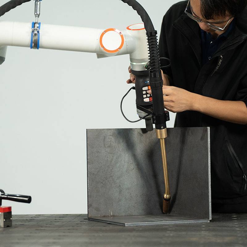
Operational Observations from the Düsseldorf Workshop
Implementing Laser Technology in a workshop environment traditionally geared toward arc welding requires a shift in spatial logic. Unlike high-power industrial robots that require massive light curtains and physical fencing, the Laser Welding Cobot operates in a “semi-collaborative” mode. However, we must be clear: the laser beam itself is a Class 4 hazard. In our Düsseldorf installation, we utilized a modular laser-safe enclosure (active cabin) that allows the operator to remain in proximity to the cobot’s control pendant while the process is shielded by IR-absorptive glass.
Teaching the Path: Cobot Accessibility
One of the most practical ‘lessons learned’ in the field was the ease of “Lead-Through” programming. A senior welder in the Düsseldorf shop, who had zero prior coding experience, was able to teach a complex 3D weld path for a bracket assembly in under 15 minutes. By physically moving the Laser Welding Cobot arm to the start and end points and defining the ‘wobble’ parameters via a tablet interface, the barrier to entry for Laser Technology has been significantly lowered.
Advanced Laser Technology: The Role of Fiber Optics
The 1070nm wavelength provided by the fiber Laser Technology used in this deployment is particularly effective for the reflective materials found in the Düsseldorf site’s inventory. We observed that the high power density allows for ‘keyhole’ welding even at lower wattages, which is the secret sauce for Thin Metal Sheet welding. The energy is absorbed so rapidly that the material reaches its melting point and solidifies before the surrounding lattice can conduct the heat away, preventing the dreaded “oil-can” warping effect common in large panels.
Lessons Learned: Gap Management and Tooling
Despite the success, the field report must highlight the limitations observed during the Düsseldorf deployment. Laser Technology is inherently less forgiving than MIG regarding “part-to-part” variation.
1. Jigging Precision
While the Laser Welding Cobot can handle minor gaps via the wobble function, Thin Metal Sheet welding still requires precision clamping. We found that a gap exceeding 25% of the material thickness resulted in inconsistent root penetration. We had to upgrade the local workshop’s manual clamps to pneumatic toggle clamps to ensure the repeatability that the cobot demands.
2. Cleanliness Requirements
In the Düsseldorf shop, we noticed that residual drawing oils on the aluminum sheets caused porosity in the laser weld. Unlike MIG, which can sometimes ‘burn off’ contaminants through the arc’s intensity, the concentrated beam of the Laser Welding Cobot can trap vaporized oils in the weld pool. A pre-weld wipe with isopropyl alcohol became a mandatory SOP (Standard Operating Procedure).
3. Gas Coverage Dynamics
We discovered that at the higher travel speeds enabled by the Laser Welding Cobot, the trailing edge of the weld was oxidizing before the gas shield could settle. We engineered a custom trailing gas shoe—a 3D-printed localized nozzle extension—to maintain an inert atmosphere over the bead for an additional 20mm behind the focal point. This was critical for the Düsseldorf client’s “medical grade” stainless steel contracts.
Economic Impact and Throughput Analysis
In the four weeks of the Düsseldorf field study, the Laser Welding Cobot produced 4,200 units. A comparative analysis with the previous manual MIG line showed:
- Throughput Increase: 320% increase in parts per hour.
- Consumable Savings: 70% reduction in shielding gas per meter of weld, and zero wire waste (as we utilized autogenous welding for 80% of the joints).
- Quality Rate: Rejection rate dropped from 4.5% (manual) to 0.2% (cobot).
Integration of Laser Technology into the Local Workforce
The “Düsseldorf Model” we’ve developed focuses on the welder as a ‘Process Supervisor.’ The Laser Welding Cobot does not replace the welder’s knowledge of metallurgy or joint design; it simply executes the repetitive, high-precision motion. The synergy between the human’s ability to troubleshoot fit-up and the Laser Technology’s ability to deliver concentrated energy results in a higher tier of manufacturing capability.
Conclusion and Recommendations
The deployment of the Laser Welding Cobot in Düsseldorf has proven that for Thin Metal Sheet welding, the transition from arc-based processes to Laser Technology is commercially and technically viable. To maximize ROI, it is recommended that the facility invests in automated cleaning stations and precision-machined jigs to match the cobot’s 0.05mm repeatability.
Final takeaway: The speed and thermal control of the Laser Welding Cobot have redefined our expectations for sheet metal fabrication. We are no longer fighting the physics of heat; we are controlling it with surgical precision.
Report Prepared By: Senior Welding Engineer, Site Operations – Düsseldorf.
Date: October 2023
Subject: Field Integration Report #88-DUS
-


LT240S tube laser cutting machine
-
LT120S tube laser cutting machine
-
Sale

Tank Fillet Welding Machine
Original price was: $1,000.00.$900.00Current price is: $900.00. -
Sale

MAK100 tube laser cutting machine
Original price was: $5,500.00.$5,000.00Current price is: $5,000.00. -

portable plasma air cutting machine
$1,200.00 -

2in1 fiber laser cutting machine
-

Air cooling Laser welding machine
-

HF h beam laser cutting machine
-

LT240 laser cutting machine
-

Laser welding machine
-


Cobot Welding Station
-

Gantry welding robot solution
-

Tracked Wheeled AGV Welding robot
-

LFH6020 Fiber laser cutting machine
-
LFP6020
-

robotic welidng machine
Advanced Fiber Laser Tube Processing Technology
Our CNC Fiber Laser Tube Cutting systems revolutionize metal fabrication by integrating high-precision cutting, punching, and profiling into a single automated workflow. Designed for versatility, this technology handles a wide array of profiles including Round, Square, Rectangular, and Oval tubes, as well as complex L-shaped and U-shaped channels.
- Precision Punching: High-speed hole punching with micron-level accuracy, eliminating the need for mechanical drilling or die-stamping.
- Complex Profiling: Advanced 3D pathing allows for intricate interlocking joints and specialized notch cuts, ideal for structural frames.
- High Material Efficiency: Intelligent nesting software minimizes scrap, reducing raw material costs across large production runs.
- Clean Finish: Delivers oxide-free, burr-free edges that require zero secondary grinding before welding.

Seamlessly processing multiple profiles with consistent precision.
Global Delivery & Logistics


From our high-tech manufacturing facility directly to your global site. PCL WeldCut ensures secure packaging, professional handling, and reliable international logistics to safeguard your equipment throughout the entire journey.