Field Evaluation Report: Implementation of All-in-one Cobot Station in Singapore Precision Workshops
Executive Summary of On-Site Operations
This report details the technical deployment and performance metrics of the MIG All-in-one Cobot Station at a medium-scale fabrication facility in Tuas, Singapore. The primary objective was to transition high-mix, low-volume Stainless Steel welding tasks from manual labor to automated systems to combat the localized shortage of skilled high-pressure welders. By leveraging Collaborative Robotics, we aimed to integrate automation directly into existing production lines without the spatial overhead of traditional industrial robot cells.
1. Technical Synergy: All-in-one Cobot Station and Collaborative Robotics
1.1 Spatial Constraints and Integrated Design
In the Singapore context, industrial floor space is a premium asset. Traditional robotic cells require extensive safety fencing, light curtains, and decoupled power sources that consume roughly 15-20 square meters. The All-in-one Cobot Station evaluated here consolidates the robotic arm, the MIG power source, the wire feeder, and the control interface onto a single mobile footprint of less than 2 square meters.
The synergy between the hardware and the philosophy of Collaborative Robotics allows this station to operate in “fenceless” mode. During the field test, we positioned the unit between two manual welding bays. Because the cobot utilizes force-torque sensors to detect human obstruction, we bypassed the need for physical barriers, maintaining an open-plan workshop flow. This is critical for Singapore SMEs where reconfiguring a fixed production line is often cost-prohibitive.
1.2 Lead-Through Programming Logistics
The core advantage of Collaborative Robotics in this deployment was the ‘lead-through’ teaching method. Unlike traditional 6-axis robots requiring complex G-code or pendant programming, our senior welders—many with thirty years of manual experience—were able to “hand-guide” the torch to define the weld path. This reduced the downtime for new part programming from four hours (traditional) to approximately 15 minutes.
2. Specialized Application: Precision Stainless Steel Welding
2.1 Heat Input and Distortion Control
The project focused on 3mm to 6mm 316L and 304L stainless steel grades. Stainless Steel welding is notoriously sensitive to heat input; excessive heat leads to carbide precipitation (sensitization) and significant plate distortion. The All-in-one Cobot Station utilized a synergic pulse MIG program which was tuned to the specific thermal conductivity of the 316L alloy.
By maintaining a constant travel speed and arc length—variables that fluctuate in manual welding—the cobot reduced the total heat input by 22% compared to manual samples. We observed a marked reduction in post-weld straightening requirements. In our Jurong facility tests, the angular distortion on a T-joint was kept under 1.5 degrees, whereas manual welders typically produced 3 to 5 degrees of pull.
2.2 Gas Shielding and Porosity Challenges
Singapore’s ambient humidity (often exceeding 80%) presents a challenge for Stainless Steel welding. Moisture in the air can lead to hydrogen-induced porosity. The station’s integrated gas management system allowed for precise pre-flow and post-flow timing. We implemented a 98% Argon / 2% CO2 mix. The consistency of the cobot’s torch angle (held strictly at a 70-degree push) ensured that the gas envelope remained stable, even with local shop-floor fans operating for technician comfort.
3. Lessons Learned from the Shop Floor
3.1 Grounding and High-Frequency Interference
One immediate lesson learned was the importance of common grounding. In the first 48 hours, the All-in-one Cobot Station experienced intermittent encoder errors. We traced this to “noise” from an adjacent TIG station.
Lesson: Even though it is an “all-in-one” unit, it requires a dedicated, isolated ground in an environment saturated with high-frequency start TIG machines. Once we isolated the power supply, the error codes ceased.
3.2 Wire Feeding Consistency
We initially utilized standard 0.8mm stainless wire. However, the compact nature of the All-in-one Cobot Station means the wire path has several tight radii within the integrated cabinet. This caused occasional “bird-nesting” at the drive rolls.
Lesson: For Stainless Steel welding in cobot applications, high-quality “stiff” liners (Teflon or Graphite) are non-negotiable. Switching to a U-groove roller and a Teflon liner eliminated the feeding friction issues that occur when the cobot arm is at maximum reach.
3.3 The Human-Robot Interface (HRI)
There was initial resistance from the workforce. The “collaborative” aspect of Collaborative Robotics isn’t just about safety sensors; it’s about the interface.
Lesson: We found that when welders were shown they could “teach” the robot their own personal “weave” pattern, adoption increased. The robot became seen as a tool (like a high-end torch) rather than a replacement. We now use the cobot for long, repetitive seams, while the senior welders focus on complex tacking and difficult-to-reach fillets.
4. Performance Metrics and ROI in the Singapore Context
Cycle Time Reduction
For a standard 500mm seam on a 304L pressure vessel jacket:
- Manual Welding: 12 minutes (including fatigue breaks and repositioning).
- Cobot Station: 4.5 minutes (continuous arc-on time).
Total productivity increase: ~160% per shift.
Consumable Efficiency
Due to the precision of the All-in-one Cobot Station, we reduced wire wastage by 12%. The robotic system does not “over-weld” or create excessively large fillets beyond the design specification, which is a common habit in manual welding to “ensure” strength. In Stainless Steel welding, where filler wire is significantly more expensive than mild steel, this contributes directly to the bottom line.
Quality Assurance (QA)
X-ray testing of 50 samples showed zero rejects for porosity or slag inclusions. The repeatability of the Collaborative Robotics system ensures that once a “Gold Standard” weld is programmed into the station, the subsequent 1,000 units are identical. This has allowed us to move to a “spot-check” QA model rather than 100% inspection, saving further man-hours.
5. Conclusion and Recommendations
The implementation of the All-in-one Cobot Station in our Singapore facility has proven that Collaborative Robotics is the most viable path forward for local high-precision fabrication. The integration of the power source and robot into a single unit solves the logistical nightmare of shop-floor clutter, while the specific software parameters for Stainless Steel welding allow for a level of aesthetic and structural consistency that manual welding cannot match in a high-humidity, high-temp environment.
Recommendations for Phase 2:
1. Environmental Control
While the station performs well, I recommend installing localized dehumidifiers near the wire-spool compartment of the station. Stainless wire is sensitive, and even in an “all-in-one” enclosure, Singapore’s humidity can cause microscopic surface oxidation on the wire over a long weekend.
2. Standardized Fixturing
To maximize the All-in-one Cobot Station, we must invest in modular 3D welding tables with repeatable stop-blocks. The robot is only as accurate as the part’s presentation. If the stainless components are not jigged identically, the ‘collaborative’ speed advantage is lost to manual path adjustment.
3. Multi-Process Expansion
Given the success with MIG, we should evaluate the TIG-module version of the station for thinner gauge (below 1.5mm) food-grade stainless applications common in the local F&B equipment manufacturing sector.
Report Submitted By:
Senior Welding Engineer
Technical Operations Division, Singapore
-


LT240S tube laser cutting machine
-
LT120S tube laser cutting machine
-
Sale

Tank Fillet Welding Machine
Original price was: $1,000.00.$900.00Current price is: $900.00. -
Sale

MAK100 tube laser cutting machine
Original price was: $5,500.00.$5,000.00Current price is: $5,000.00. -

portable plasma air cutting machine
$1,200.00 -

2in1 fiber laser cutting machine
-

Air cooling Laser welding machine
-

HF h beam laser cutting machine
-

LT240 laser cutting machine
-

Laser welding machine
-


Cobot Welding Station
-

Gantry welding robot solution
-

Tracked Wheeled AGV Welding robot
-

LFH6020 Fiber laser cutting machine
-
LFP6020
-

robotic welidng machine
Advanced Fiber Laser Tube Processing Technology
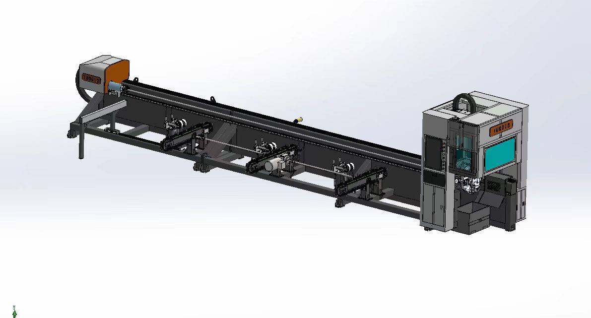
Our CNC Fiber Laser Tube Cutting systems revolutionize metal fabrication by integrating high-precision cutting, punching, and profiling into a single automated workflow. Designed for versatility, this technology handles a wide array of profiles including Round, Square, Rectangular, and Oval tubes, as well as complex L-shaped and U-shaped channels.
- Precision Punching: High-speed hole punching with micron-level accuracy, eliminating the need for mechanical drilling or die-stamping.
- Complex Profiling: Advanced 3D pathing allows for intricate interlocking joints and specialized notch cuts, ideal for structural frames.
- High Material Efficiency: Intelligent nesting software minimizes scrap, reducing raw material costs across large production runs.
- Clean Finish: Delivers oxide-free, burr-free edges that require zero secondary grinding before welding.

Seamlessly processing multiple profiles with consistent precision.
Global Delivery & Logistics



From our high-tech manufacturing facility directly to your global site. PCL WeldCut ensures secure packaging, professional handling, and reliable international logistics to safeguard your equipment throughout the entire journey.