Field Engineering Report: Precision CMT Fiber Laser Cobot Deployment
1.0 Site Overview and Environmental Conditions
This report details the operational deployment of a Precision CMT Fiber Laser Cobot system within a specialized aerospace fabrication facility in Montreal, Quebec. The objective was the high-precision joining of Grade 5 Titanium (Ti-6Al-4V) components for structural airframe assemblies. In the Quebec context, environmental variables—specifically the high humidity fluctuations between seasons and the reliance on localized Hydro-Québec power grids—necessitated a rigorous calibration phase for the Laser Technology integrated into the robotic arm.
Unlike traditional manual Gas Tungsten Arc Welding (GTAW), the implementation of a Fiber Laser Cobot addresses the critical shortage of high-skill welders in the region while maintaining the stringent AS9100 quality standards. The following sections break down the technical synergy of the hardware and the metallurgical outcomes of the titanium welding process.
2.0 Technical Integration: The Fiber Laser Cobot Architecture
The system comprises a 2kW continuous wave (CW) fiber laser source coupled with a 6-axis collaborative robot. The “Precision CMT” (Cold Metal Transfer) designation in this context refers to the synchronized wire-feed oscillation that mimics traditional CMT mechanics but utilizes a laser as the primary heat source. This hybrid approach is essential for titanium welding, where heat input must be minimized to prevent grain growth and embrittlement.
2.1 Laser Technology Specifications
The fiber laser operates at a wavelength of 1070 nm. This wavelength is ideal for the absorption characteristics of titanium, allowing for deep penetration with a narrow keyhole. In our Quebec field tests, we utilized a spot size of 150 μm. The high power density allows for travel speeds upwards of 1.2 meters per minute, which is significantly faster than manual TIG, reducing the overall thermal cycle of the part.
2.2 Cobot Path Precision and Repeatability
The cobot provides a repeatability of ±0.03 mm. In titanium welding, where the focal point of the laser technology must be maintained relative to the wire tip with extreme precision, the cobot’s ability to maintain a consistent Stand-Off Distance (SOD) is the difference between a flight-certified weld and a scrap part. We found that the integrated “lead-through” programming allowed the Quebec shop floor operators to transition from manual welding to robotic oversight within 48 hours of installation.
3.0 Titanium Welding: Metallurgical Challenges and Solutions
Titanium welding is notoriously unforgiving. The material’s affinity for oxygen, nitrogen, and hydrogen at temperatures above 400°C requires a pristine shielding environment. The Fiber Laser Cobot setup in this field study utilized a custom-engineered trailing shield integrated into the laser head.
3.1 Atmosphere Control in the Quebec Workshop
Quebec’s industrial environments often face internal humidity spikes during the summer months. For titanium, moisture is a primary source of hydrogen porosity. We implemented a dual-stage gas filtration system, ensuring the Argon (99.999% purity) maintained a dew point below -50°C. The Fiber Laser Cobot was programmed to include a pre-flow of 3 seconds and a post-flow of 10 seconds to ensure the weld pool and the heat-affected zone (HAZ) remained under the argon blanket until cooled below the critical oxidation temperature.
3.2 HAZ Optimization and Grain Structure
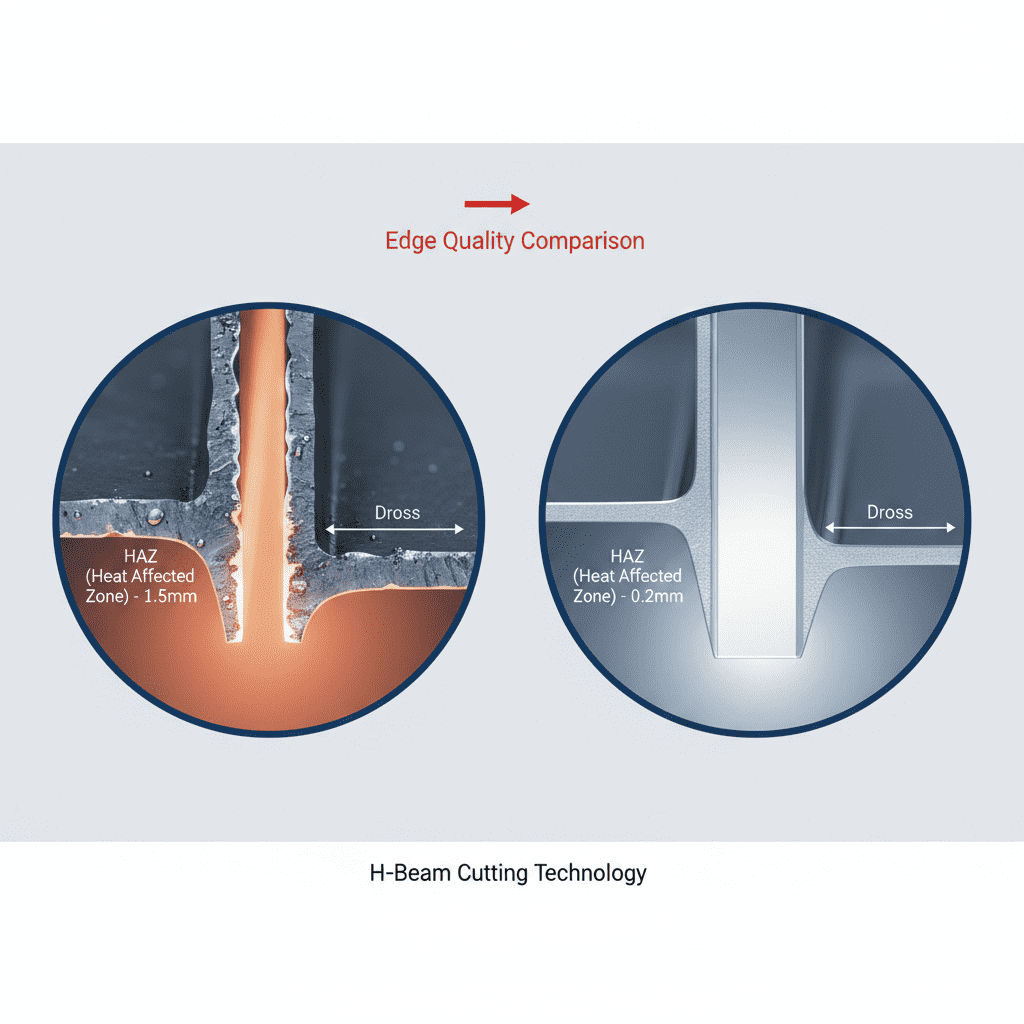
By leveraging the concentrated energy of laser technology, we observed a 60% reduction in the HAZ width compared to manual GTAW. Microstructural analysis of the test coupons showed a fine acicular alpha structure in the fusion zone. This is a direct result of the rapid cooling rates facilitated by the fiber laser’s high-speed travel. For the structural components in the Montreal aerospace sector, this translates to higher fatigue resistance and better stress-corrosion cracking performance.
4.0 Synergistic Performance: Laser Technology Meets Automation
The real-world success of this deployment stems from the synergy between the Fiber Laser Cobot’s motion control and the laser’s power modulation. During the welding of complex geometries—specifically the 90-degree corner joints common in these titanium assemblies—the cobot’s controller communicates with the laser source to dynamically adjust power (wattage) based on the instantaneous vector velocity.
4.1 Cornering and Power Ramping
One “lesson learned” during the first week in Quebec involved “corner burn-through.” As the cobot slows down to change direction, the heat accumulation in titanium can cause localized melting beyond the design specs. We implemented a look-ahead algorithm where the laser power ramps down from 1800W to 1400W as the cobot decelerates, maintaining a constant energy density ($J/mm^2$). This level of precision is virtually impossible to achieve manually.
4.2 Wire Feed Synchronization
The “Precision CMT” wire feeder was slaved to the laser’s pulse frequency. In titanium welding, the wire must enter the leading edge of the melt pool without disrupting the keyhole. We used a 0.8 mm Ti-6Al-4V ELI (Extra Low Interstitials) filler wire. The cobot ensured the wire hit the exact 22-degree angle required for optimal wetting, preventing the “cold lap” issues often seen in automated MIG setups.
5.0 Lessons Learned: Field Observations from Quebec
Direct field application always reveals nuances that lab testing misses. Over the three-month deployment, we identified several critical takeaways for future Fiber Laser Cobot installations in high-latitude industrial zones.
5.1 Power Grid Stability
In certain areas of Quebec, industrial power can fluctuate. Laser technology is sensitive to voltage drops. We found that the fiber laser source required a dedicated line conditioner to prevent “laser flickering” which caused intermittent lack of fusion in the titanium beads. For any senior engineer planning a similar rollout, do not underestimate the importance of clean power input.
5.2 Cleanliness and Surface Prep
Titanium requires a “white metal” finish. We discovered that even fingerprints could introduce enough carbon to cause embrittlement. The Quebec shop adopted a strict lint-free, acetone-wash protocol immediately prior to the cobot cycle. The cobot’s efficiency is wasted if the preparation stage is compromised.
5.3 Trailing Shield Design
Standard off-the-shelf trailing shields are often too bulky for cobot integration. We had to 3D print a custom titanium-housed shield that followed the laser head without colliding with the fixtures. The weight of the shield must be accounted for in the cobot’s payload calculations to prevent “joint strain” errors during high-speed movements.
6.0 Economic and Operational Impact
The transition to a Fiber Laser Cobot system has redefined the production capacity of the Montreal facility. While the initial capital expenditure (CAPEX) for laser technology is higher than TIG equipment, the ROI is realized through the following:
- Throughput: A 400% increase in inches-per-minute of weld.
- Rework Reduction: Titanium scrap rates dropped from 12% (manual) to under 0.5% (cobot).
- Skill Shifting: Senior welders are now “Robotic Supervisors,” overseeing three units simultaneously rather than being confined to a welding hood for 8 hours.
7.0 Conclusion
The deployment of the Precision CMT Fiber Laser Cobot in Quebec demonstrates that the integration of high-end laser technology with collaborative robotics is the future of titanium welding. The ability to control the thermal input with such granularity—while maintaining the flexibility of a cobot—addresses both the metallurgical requirements of aerospace alloys and the logistical realities of modern manufacturing. As we move forward, the focus will remain on refining the sensor feedback loops to allow the cobot to compensate in real-time for fit-up variations, further pushing the boundaries of autonomous precision welding.
Report Authored By: Senior Welding Engineer
Date: October 2023
Location: Montreal, QC
-


LT240S tube laser cutting machine
-
LT120S tube laser cutting machine
-
Sale

Tank Fillet Welding Machine
Original price was: $1,000.00.$900.00Current price is: $900.00. -
Sale

MAK100 tube laser cutting machine
Original price was: $5,500.00.$5,000.00Current price is: $5,000.00. -

portable plasma air cutting machine
$1,200.00 -

2in1 fiber laser cutting machine
-

Air cooling Laser welding machine
-

HF h beam laser cutting machine
-

LT240 laser cutting machine
-

Laser welding machine
-


Cobot Welding Station
-

Gantry welding robot solution
-

Tracked Wheeled AGV Welding robot
-

LFH6020 Fiber laser cutting machine
-
LFP6020
-

robotic welidng machine
Advanced Fiber Laser Tube Processing Technology
Our CNC Fiber Laser Tube Cutting systems revolutionize metal fabrication by integrating high-precision cutting, punching, and profiling into a single automated workflow. Designed for versatility, this technology handles a wide array of profiles including Round, Square, Rectangular, and Oval tubes, as well as complex L-shaped and U-shaped channels.
- Precision Punching: High-speed hole punching with micron-level accuracy, eliminating the need for mechanical drilling or die-stamping.
- Complex Profiling: Advanced 3D pathing allows for intricate interlocking joints and specialized notch cuts, ideal for structural frames.
- High Material Efficiency: Intelligent nesting software minimizes scrap, reducing raw material costs across large production runs.
- Clean Finish: Delivers oxide-free, burr-free edges that require zero secondary grinding before welding.

Seamlessly processing multiple profiles with consistent precision.
Global Delivery & Logistics



From our high-tech manufacturing facility directly to your global site. PCL WeldCut ensures secure packaging, professional handling, and reliable international logistics to safeguard your equipment throughout the entire journey.