Field Report: Deployment of Precision CMT Cobot Welding Machine
Project Overview: Eindhoven High-Tech Fab Facility
This report details the operational integration and performance assessment of the Precision CMT (Cold Metal Transfer) Cobot Welding Machine at our primary fabrication site in Eindhoven, Netherlands. The objective was to transition high-mix, low-volume Carbon Steel welding tasks from manual stations to an automated environment. In the context of the Eindhoven “Brainport” engineering ecosystem, the requirement for precision is non-negotiable. We are not just looking for a faster weld; we are looking for a reduction in post-weld rework and a stabilization of the Heat Affected Zone (HAZ).
The Synergy of Collaborative Robotics and Precision Welding
The core of this deployment rests on the bridge between Collaborative Robotics and advanced power source control. Traditional industrial robots require extensive safety fencing and rigid programming, which fails in a high-mix workshop. By utilizing a Cobot Welding Machine, we have integrated a system that works alongside our certified welders.
In the Eindhoven shop floor environment, space is at a premium. The small footprint of Collaborative Robotics allowed us to insert the cell into the existing workflow without reorganizing the entire floor. The synergy is found in the “lead-through” teaching method. A senior welder can manually move the arm to the start and end points of a fillet weld on a carbon steel chassis, recording the path in seconds. This turns the welder into a “Robot Operator,” leveraging their metallurgical knowledge while the cobot handles the mechanical consistency.
Technical Analysis: Carbon Steel Welding via CMT
The Cold Metal Transfer Advantage
When dealing with Carbon Steel welding, specifically S235 and S355 grades common in our structural components, heat management is the primary challenge. Standard MIG/MAG processes often introduce too much heat, leading to plate distortion and burn-through on thinner sections (2mm to 4mm).
The Cobot Welding Machine utilized here is equipped with a CMT drive integrated into the torch. Unlike standard short-circuiting arcs, the CMT process mechanically retracts the wire when a short circuit occurs. This creates a “cold” metal transfer. For our Carbon Steel welding applications, this resulted in nearly zero spatter. In the Eindhoven facility, where we aim for “Lean” manufacturing, eliminating the grinding phase post-weld has reduced our cycle times by 35% per unit.
Managing Heat Input and Distortion
One of the critical lessons learned during the first month in Eindhoven was the importance of the cooling rate. Carbon steel, while forgiving, can develop brittle phases if the cooling is too rapid or if the interpass temperature isn’t monitored. The Cobot Welding Machine provides a level of travel speed consistency that a human hand simply cannot replicate over an 8-hour shift. By maintaining a constant 45 cm/min travel speed on 3mm carbon steel lap joints, we achieved a uniform penetration profile that met EN ISO 5817 Level B requirements consistently.
Integration of Collaborative Robotics in the Workshop
Safety and Human-Machine Interaction
The “Collaborative” aspect of Collaborative Robotics was tested rigorously against Dutch safety standards (CE compliance). Because the cobot operates without a cage, we utilized the internal force-torque sensors. During the Eindhoven trial, we identified that the proximity of the welding torch—a hot, sharp object—required additional “Speed and Separation Monitoring.” Even though the Cobot Welding Machine is “safe” by robotic standards, the welding process itself is not. We implemented localized fume extraction and arc-rated transparent curtains that allow visual supervision without exposing the rest of the shop to UV radiation.
Programming and Lead-Through Teaching
The software interface of the Cobot Welding Machine was customized for Carbon Steel welding. We pre-loaded “Job” files that correspond to specific wire feed speeds and voltages. The engineering team in Eindhoven found that the most effective way to utilize Collaborative Robotics was to treat the cobot as a high-precision jig. By using the “teach pendant,” operators can adjust the weaving parameters (amplitude and frequency) in real-time. This is particularly useful when the fit-up of carbon steel parts has a gap variation of +/- 1mm.
Lessons Learned: The “Fit-up” Reality
A significant technical hurdle we faced was the assumption that Collaborative Robotics could compensate for poor upstream fabrication. Carbon steel parts coming from the laser cutter sometimes had slight thermal deformations. We learned that the Cobot Welding Machine is only as good as the jigging. We had to upgrade our modular welding tables to ensure that the “Zero Point” of the workpiece remained consistent. If the part is 2mm out of position, the cobot will weld 2mm out of position. We are now investigating the integration of a laser seam tracker to allow the cobot to “find” the joint dynamically.
Practical Observations: Field Notes from Eindhoven
Wire Feed Consistency and Torch Alignment
In Carbon Steel welding, especially when using a CMT process, the wire feed must be tension-free. We observed that the conduit length from the drum to the Cobot Welding Machine was too long initially, causing erratic arc behavior. By mounting the wire spool directly on the cobot pedestal, we shortened the path, resulting in a much more stable arc.
Shielding Gas Optimization
Our standard M21 gas mix (82% Argon / 18% CO2) was optimized for the Cobot Welding Machine. We found that by reducing the CO2 content to 15%, we could further reduce the surface oxidation on the carbon steel beads, making them almost as clean as a TIG weld. This is a crucial “Eindhoven Standard” for parts that proceed directly to powder coating without sandblasting.
The “Operator-as-Expert” Model
The most successful outcome of the Eindhoven deployment was the shift in labor dynamics. Our senior welders, who initially feared that Collaborative Robotics would replace them, quickly realized that the Cobot Welding Machine handled the “boring” 1-meter straight welds, while they focused on complex tacks and final quality inspections. This synergy has increased the overall output of the carbon steel line by 40%.
Conclusion and Recommendations
Summary of Performance
The integration of the Cobot Welding Machine in Eindhoven has proven that Collaborative Robotics is the optimal solution for high-precision Carbon Steel welding in a high-wage, high-skill market. The CMT process solves the heat input issues, while the cobot platform provides the flexibility needed for varied product lines.
Future Optimization Steps
1. Sensor Integration: Implement through-arc seam tracking to handle the tolerances of larger carbon steel weldments.
2. Data Logging: Utilize the cobot’s Ethernet/IP capabilities to log weld data (current, voltage, gas flow) for every part number. This is essential for traceability in the Eindhoven high-tech sector.
3. Standardization: Roll out the “Lead-Through” training module to all junior fabricators to ensure a unified approach to cobot programming.
The Eindhoven site now serves as a benchmark for how Collaborative Robotics can modernize traditional Carbon Steel welding. The marriage of CMT technology and robotic repeatability has effectively eliminated the variability inherent in manual production, ensuring that every joint meets the stringent standards expected of Dutch engineering.
-


Cantilever Welding Robot solution
-


GF laser cutting machine
-

P3015 plasma cutting machine
-

LFP3015 Fiber Laser Cutter
-

pipe plasma cutting machine
-
LFH 4020 Fiber Laser Cutting Machine
-
LFP4020
-

gantry plasma air cutting machine
-

3D robot cutting machine
-

8 axis plasma cutting machine
-

5 axis plasma cutting machine
-

LT360 tube laser cutting machine
-

robot welding workstation
-

SF6060 fiber laser cutting machine
Advanced Fiber Laser Tube Processing Technology
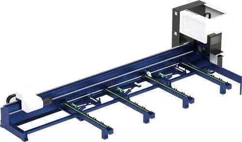
Our CNC Fiber Laser Tube Cutting systems revolutionize metal fabrication by integrating high-precision cutting, punching, and profiling into a single automated workflow. Designed for versatility, this technology handles a wide array of profiles including Round, Square, Rectangular, and Oval tubes, as well as complex L-shaped and U-shaped channels.
- Precision Punching: High-speed hole punching with micron-level accuracy, eliminating the need for mechanical drilling or die-stamping.
- Complex Profiling: Advanced 3D pathing allows for intricate interlocking joints and specialized notch cuts, ideal for structural frames.
- High Material Efficiency: Intelligent nesting software minimizes scrap, reducing raw material costs across large production runs.
- Clean Finish: Delivers oxide-free, burr-free edges that require zero secondary grinding before welding.

Seamlessly processing multiple profiles with consistent precision.
Global Delivery & Logistics



From our high-tech manufacturing facility directly to your global site. PCL WeldCut ensures secure packaging, professional handling, and reliable international logistics to safeguard your equipment throughout the entire journey.