Engineering Review: Precision CMT Automated MAG Welding Cell – Paris, France

In this article
- Field Engineering Report: Commissioning of Precision CMT Automated MAG Welding Cell
- Location: Industrial Precinct, Saint-Denis (Paris, France)
- Technical Breakdown: The Automated MAG Welding Cell
- The Role of Specialized Arc Welding Solutions
- Challenges in Stainless Steel Welding: Distortion Management
- Synergy in the Field: Lessons Learned
- Parisian Workshop Constraints: Space and Power
- Final Engineering Summary
Field Engineering Report: Commissioning of Precision CMT Automated MAG Welding Cell
Location: Industrial Precinct, Saint-Denis (Paris, France)
Overview of the Site Deployment
The deployment in the Paris workshop was driven by a need to transition from high-labor manual TIG processes to a high-throughput Automated MAG Welding Cell. The facility handles complex 304L and 316L stainless steel assemblies for the European food and beverage sector. Given the high cost of skilled labor in France and the stringent aesthetic requirements of the final product, the integration of specialized **Arc Welding Solutions** was not a luxury—it was a technical necessity.
The primary challenge was managing the thermal input on 2.0mm thin-wall stainless steel tubing while maintaining a travel speed that justified the capital expenditure of the robotic cell.
Technical Breakdown: The Automated MAG Welding Cell
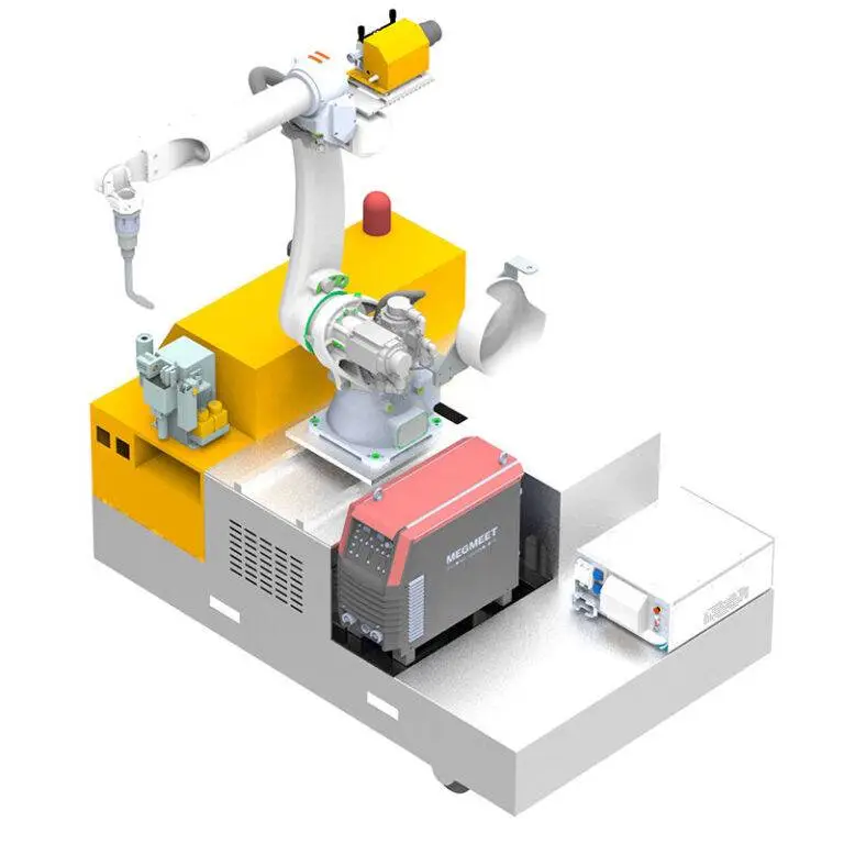
The heart of the installation is a 6-axis robotic arm integrated with a Fronius TPS/i power source, specifically utilizing the Cold Metal Transfer (CMT) process. When we discuss an Automated MAG Welding Cell in this context, we are referring to more than just the robot. We are looking at a closed-loop system where the wire feed is synchronized with the arc length and the digital power source.
CMT Integration and Wire Feed Control
In this Paris-based project, the “Cold” aspect of the MAG process was critical. Conventional MAG (Metal Active Gas) welding often creates excessive spatter and a large Heat Affected Zone (HAZ), which leads to post-weld cleaning costs. By utilizing the CMT cycle—where the wire is physically retracted when a short circuit is detected—we achieved a droplet transfer that is nearly heat-free compared to traditional spray or globular transfer.
The synergy between the Automated MAG Welding Cell and the Arc Welding Solutions platform allowed us to program specific start/stop sequences that eliminate crater cracks, a common failure point in Stainless Steel welding.
The Role of Specialized Arc Welding Solutions
In a high-precision environment, “Arc Welding Solutions” refers to the holistic integration of hardware, software, and gas chemistry. In Paris, we encountered an issue with gas turbulence caused by the facility’s high-volume HVAC system.
Shielding Gas Optimization
For the Stainless Steel welding phase, we utilized a ternary gas mixture (Ar/He/CO2). The Helium component increases the thermal conductivity of the arc, allowing for better wetting of the toes of the weld without increasing the overall current. This is a critical component of the broader Arc Welding Solutions package. We found that a flow rate of 16 L/min was the “sweet spot” to counteract the workshop’s ambient drafts while preventing the turbulence that causes porosity.
Synergic Programming
The automation allows us to use “synergic lines”—pre-programmed data sets where the voltage and wire feed speed are locked in a ratio optimized for the material. For the Paris team, we customized these lines specifically for 1.2mm 316LSi wire. The automation ensures that whether the robot is at 10% or 90% of its travel speed, the arc characteristics remain identical.
Challenges in Stainless Steel Welding: Distortion Management
The greatest enemy in this field report was thermal distortion. Stainless steel has a high coefficient of thermal expansion and low thermal conductivity. In a manual setup, the welder spends 40% of their time “tacking” and straightening.
The Automated Solution
By moving to an Automated MAG Welding Cell, we implemented a “staggered” welding sequence. The robot doesn’t weld a circular joint in one pass; it performs two 180-degree segments starting from opposite poles. This balance of heat input is only possible with the precision of robotic path planning.
Furthermore, the CMT process reduced the total heat input by approximately 30% compared to pulsed MAG. This reduction meant that the assemblies remained within the ±0.5mm tolerance required for the subsequent assembly stage in the Paris line without the need for water-cooled jigs.
Synergy in the Field: Lessons Learned
The interaction between the Automated MAG Welding Cell and the broader Arc Welding Solutions ecosystem taught us several hard lessons during the three-week commissioning phase.
1. The Grounding (Earthing) Factor
We initially saw erratic arc behavior during the first week. In a high-frequency automated environment, the return lead (earth) must be impeccable. In the Paris shop, the paint on the jigging tables was insulating the workpieces just enough to cause “arc hunting.”
*Lesson:* Ensure a direct, rotating earth connection for any automated lathe or turn-table integrated into the cell.
2. Contact Tip Longevity
Stainless Steel welding is notoriously hard on contact tips due to the abrasive nature of the wire and the heat reflected from the weld pool. We switched to zirconium-chrome-copper tips. While more expensive, they reduced the downtime of the Automated MAG Welding Cell by 15%, as we no longer had to recalibrate the Tool Center Point (TCP) every four hours due to tip erosion.
3. Torch Angle and Spatter
Even with CMT, the torch angle is vital. We found that a “push” angle of 10 to 15 degrees provided the best gas coverage and bead profile. If the robot dropped to a 0-degree (perpendicular) angle, we saw a slight increase in surface oxidation (blackening), which required manual pickling.
Parisian Workshop Constraints: Space and Power
The workshop in Paris had a limited footprint. This forced us to consolidate the Arc Welding Solutions equipment. We opted for a “top-mount” wire feeder on the robot’s third axis. This reduced the length of the umbilical cable, which is crucial for CMT. If the wire liner is too long, the mechanical retraction of the wire (the “back-and-forth” motion) loses its frequency, and the arc becomes unstable.
Efficiency Metrics
* Old Process (Manual TIG): 12 units per shift.
* New Process (Automated MAG): 55 units per shift.
* Reject Rate: Dropped from 8% to 0.5%.
Final Engineering Summary
The success of this installation was not just about the robot; it was about the technical synergy between the Automated MAG Welding Cell and the specialized Arc Welding Solutions tailored for Stainless Steel welding. By focusing on the CMT process, we effectively mitigated the inherent weaknesses of stainless steel—namely, heat distortion and oxidation.
The Paris site is now a benchmark for our European operations. The transition proves that MAG welding, when automated and controlled via CMT, can match the quality of TIG while providing the speed necessary for modern industrial scaling. The key takeaway for the engineering team is to never underestimate the importance of the “small” variables: gas chemistry, liner length, and earthing. The robot is only as good as the arc it carries.
Report End.
*Senior Welding Engineer*
*Paris Commissioning Phase*