Field Engineering Report: Implementation of Precision CMT within an Automated MAG Welding Cell
1. Project Scope and Environmental Context (Hanoi, Vietnam)
This report details the technical commissioning and operational optimization of a high-precision Automated MAG Welding Cell at a Tier-1 automotive component facility in the Thang Long Industrial Park, Hanoi. The primary objective was to transition from manual Metal Active Gas (MAG) stations to a fully integrated robotic system to handle high-volume mild steel welding of chassis reinforcements.
Engineering in the Hanoi region presents specific environmental challenges, primarily regarding ambient humidity and temperature fluctuations. During the commissioning phase in Q3, relative humidity levels frequently exceeded 85%. For mild steel welding, this necessitates a rigorous focus on the integrity of Arc Welding Solutions, specifically concerning shielding gas dew points and the hygroscopic nature of surface contaminants on ER70S-6 wire. The synergy between the Automated MAG Welding Cell and the peripheral climate control systems was the first major hurdle addressed in this deployment.
2. Technical Configuration of the Automated MAG Welding Cell
The cell architecture consists of a 6-axis industrial manipulator integrated with a Fronius Cold Metal Transfer (CMT) power source. This specific configuration was selected because traditional “hot” MAG processes were causing excessive burn-through on 1.5mm to 2.0mm mild steel sections. The CMT process, a subset of the broader Arc Welding Solutions portfolio, allows for a “cold” droplet detachment by mechanically oscillating the wire, synchronized with the digital inverter’s pulse profile.
2.1. Manipulator and Torch Integration
The Automated MAG Welding Cell utilizes a hollow-wrist design to minimize cable fatigue during high-speed air moves. We implemented a tandem-table positioner (H-frame) to allow for simultaneous loading/unloading and welding. This maximizes the duty cycle of the arc, moving the bottleneck from the welding process itself to the upstream jigging department. The integration of a tactile laser sensor for seam tracking was necessary to compensate for the slight thermal distortions inherent in mild steel welding of long-seam components.
3. Optimizing Arc Welding Solutions for Mild Steel
While the hardware provides the platform, the “Solution” aspect refers to the fine-tuning of the synergy between the gas mixture, wire chemistry, and the digital weld parameters. In Hanoi, we sourced a local 82% Argon / 18% CO2 shielding gas. However, initial porosity tests indicated that the gas delivery lines in the factory were prone to moisture ingress.
3.1. Addressing Hydrogen Susceptibility
In mild steel welding, hydrogen-induced cracking is less common than in high-tensile steels, but porosity remains a significant threat to NDT (Non-Destructive Testing) compliance. We upgraded the Arc Welding Solutions package to include high-purity flow meters and dedicated wire heaters within the Automated MAG Welding Cell. By pre-heating the wire to 60°C before it reached the feed rollers, we effectively eliminated moisture-related porosity that had plagued the manual lines during the monsoon season.
4. Parameter Development and Heat Input Management
The core of this field report lies in the transition from standard globular transfer to the CMT-advanced mode. In mild steel welding, managing the Heat Affected Zone (HAZ) is critical for maintaining the structural integrity of the base metal. Traditional Arc Welding Solutions often rely on high-voltage spray transfer which, while fast, creates significant spatter and distortion on thin-gauge materials.
4.1. Comparative Data: Standard MAG vs. CMT MAG
- Standard MAG: Current: 210A, Voltage: 24V, Travel Speed: 45 cm/min. Result: High spatter, 3mm distortion over 500mm length.
- CMT Automated MAG Welding Cell: Current: 185A (Equivalent), Voltage: 16.5V, Travel Speed: 75 cm/min. Result: Zero spatter, 0.8mm distortion, 40% reduction in post-weld cleaning time.
The implementation of the Automated MAG Welding Cell allowed for a significant increase in travel speed. Because the CMT process provides a stable arc at lower voltages, we could push the robot to 75 cm/min without risking undercut—a common failure mode in manual mild steel welding when operators attempt to match robotic speeds.
5. Lessons Learned: Jigging and Tolerance Control
One of the most critical lessons learned in the Hanoi workshop was that an Automated MAG Welding Cell is only as good as the upstream fit-up. In manual mild steel welding, a skilled welder can compensate for a 1.5mm gap by weaving the torch. A robot, without expensive vision systems, will simply burn through or leave a void.
5.1. Geometric Consistency
We found that the stamped mild steel components had a variance of ±1.2mm due to aging die sets in the stamping department. To make the Arc Welding Solutions truly “robust,” we had to re-engineer the pneumatic clamping in the weld cell. We introduced “floating” clamps that register the part based on the weld joint center-line rather than the outer edge. This adjustment reduced the scrap rate from 8% to 0.4% within the first month of operation.
6. Maintenance and Consumable Lifecycle
In the tropical climate of Northern Vietnam, the maintenance schedule for an Automated MAG Welding Cell must be accelerated. The high humidity leads to faster oxidation of the copper contact tips. We observed that after 4 hours of continuous arcing, the contact tip orifice would expand by 0.15mm, leading to arc instability.
6.1. The “Solution” to Consumable Wear
Our Arc Welding Solutions included the installation of an automated torch cleaning station (reamer) with a programmed spray of anti-spatter fluid. However, the anti-spatter fluid itself was attracting dust from the nearby grinding bay. Lesson learned: Isolate the Automated MAG Welding Cell from the grinding area using positive pressure ventilation or physical partitioning. Once the cell was isolated, contact tip life increased by 200%, and the consistency of the mild steel welding beads improved visibly.
7. Synergy and System Integration
The success of this installation in Hanoi was not due to the robot or the power source alone, but the synergy between the Automated MAG Welding Cell and the broader Arc Welding Solutions infrastructure. This includes the PLC (Programmable Logic Controller) communication that allows the power source to “talk” to the robot in real-time, adjusting wire feed speeds during cornering to maintain a constant fillet size.
For mild steel welding, this level of integration is often overlooked. Engineers assume that because mild steel is “forgiving,” high-end automation is overkill. On the contrary, the high-volume nature of these components means that a 10-second saving in cycle time per part, achieved through precision CMT control, translates to thousands of dollars in annual savings.
8. Conclusion and Future Recommendations
The deployment of the Automated MAG Welding Cell in Hanoi has proven that even in challenging environmental conditions, precision mild steel welding is achievable at scale. The key is not just purchasing hardware, but implementing a comprehensive Arc Welding Solution that accounts for material prep, gas quality, and localized climate factors.
8.1. Final Engineering Summary
- Process: CMT MAG is superior to traditional MAG for thin-gauge mild steel due to reduced HAZ.
- Environment: Humidity control is non-negotiable for ER70S-6 wire storage and delivery.
- Upstream: Stamping tolerances must be tightened or compensated for with adaptive clamping within the cell.
- Synergy: The “Solution” must encompass the software, the gas, and the maintenance routine, not just the arc parameters.
As the Hanoi facility moves toward Industry 4.0, the next step will be the integration of cloud-based data monitoring within the Automated MAG Welding Cell to track gas consumption and arc-on time in real-time, further refining the Arc Welding Solutions for the next generation of mild steel welding projects.
-


Cantilever Welding Robot solution
-


GF laser cutting machine
-

P3015 plasma cutting machine
-

LFP3015 Fiber Laser Cutter
-

pipe plasma cutting machine
-
LFH 4020 Fiber Laser Cutting Machine
-
LFP4020
-

gantry plasma air cutting machine
-

3D robot cutting machine
-

8 axis plasma cutting machine
-

5 axis plasma cutting machine
-

LT360 tube laser cutting machine
-

robot welding workstation
-

SF6060 fiber laser cutting machine
Advanced Fiber Laser Tube Processing Technology
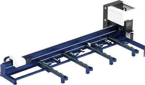
Our CNC Fiber Laser Tube Cutting systems revolutionize metal fabrication by integrating high-precision cutting, punching, and profiling into a single automated workflow. Designed for versatility, this technology handles a wide array of profiles including Round, Square, Rectangular, and Oval tubes, as well as complex L-shaped and U-shaped channels.
- Precision Punching: High-speed hole punching with micron-level accuracy, eliminating the need for mechanical drilling or die-stamping.
- Complex Profiling: Advanced 3D pathing allows for intricate interlocking joints and specialized notch cuts, ideal for structural frames.
- High Material Efficiency: Intelligent nesting software minimizes scrap, reducing raw material costs across large production runs.
- Clean Finish: Delivers oxide-free, burr-free edges that require zero secondary grinding before welding.

Seamlessly processing multiple profiles with consistent precision.
Global Delivery & Logistics



From our high-tech manufacturing facility directly to your global site. PCL WeldCut ensures secure packaging, professional handling, and reliable international logistics to safeguard your equipment throughout the entire journey.