Field Report: Optimization of Precision CMT Automated MAG Welding Cell
Project Overview: Frankfurt Automotive Component Facility
This report summarizes the final commissioning and parameter optimization phase for the newly installed Automated MAG Welding Cell at our Frankfurt assembly plant. The primary objective was to transition from manual TIG processes to a high-speed, robotic Arc Welding Solutions framework specifically designed for Thin Metal Sheet welding (0.8mm to 1.5mm thickness) on high-strength automotive alloys.
The Frankfurt facility operates under stringent Industry 4.0 protocols, requiring 100% data logging of weld parameters. Our implementation focused on the integration of Cold Metal Transfer (CMT) technology within a 6-axis robotic environment. The following technical breakdown details the synergy between hardware, software, and metallurgical constraints encountered during the 14-day field assessment.
The Automated MAG Welding Cell: System Architecture
The core of the installation is a Automated MAG Welding Cell consisting of a Fanuc ARC Mate 100iD manipulator integrated with a Fronius TPS 400i CMT power source. Unlike conventional MAG (Metal Active Gas) setups, the CMT process utilized here relies on a high-speed wire retraction mechanism. This mechanical oscillation of the wire is synchronized with the digital power source to detach droplets during a short circuit at near-zero current.
Hardware Configuration
The cell includes a twin-table rotary positioner to maximize the duty cycle. While the robot welds on Table A, the operator loads Table B. This Automated MAG Welding Cell is equipped with a torch cleaning station (reamer) and an automated wire cutter to ensure consistent arc-start stick-out. A critical addition to the Frankfurt setup was the high-accuracy “Touch Sensing” and “Thru-Arc Seam Tracking” (TAST). In the context of Thin Metal Sheet welding, even a 0.5mm deviation in seam tracking can lead to edge-burn or lack of fusion, making the integration of these Arc Welding Solutions non-negotiable.
Synergy of Arc Welding Solutions in a High-Precision Environment
The success of the Frankfurt installation hinges on the synergy between the physical Automated MAG Welding Cell and the digital Arc Welding Solutions that govern it. In the Frankfurt workshop, we faced an immediate challenge: the ambient electromagnetic interference (EMI) from the adjacent high-frequency induction hardening line.
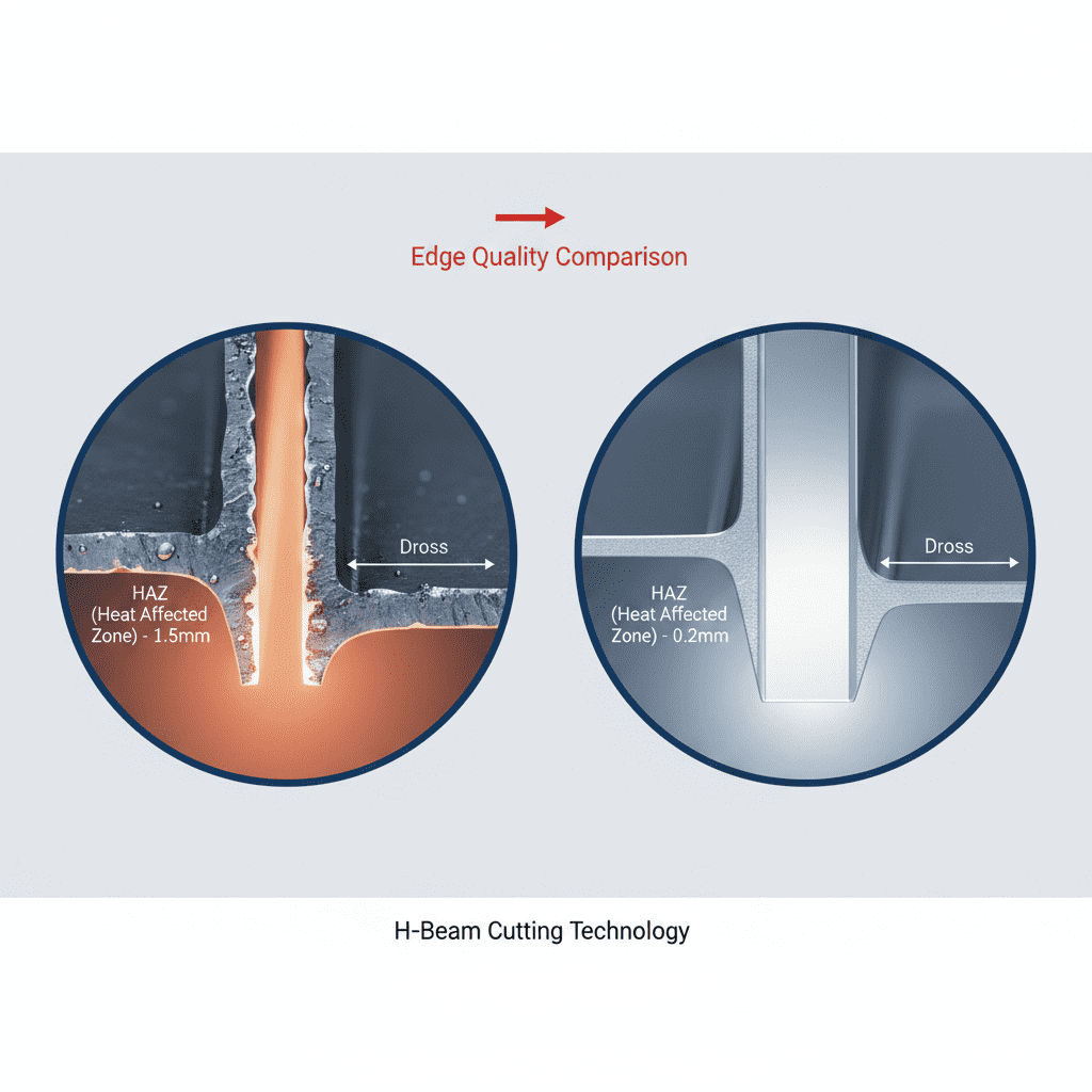
To counter this, we deployed a localized Ethernet/IP communication protocol between the robot controller and the power source. This ensured that the “Weld Start” and “Gas Pre-flow” commands had a latency of less than 2ms. The Arc Welding Solutions implemented also included a centralized gas mixing station, delivering a precise 92% Argon / 8% CO2 mixture. This specific ratio was optimized to stabilize the arc plasma while minimizing the Heat Affected Zone (HAZ), a vital consideration for the integrity of thin-gauge materials.
Software and Monitoring
The “Solution” aspect extends to the WeldCube monitoring software. Every weld bead deposited in the Frankfurt cell is mapped against its voltage/current signature. During the first week, we identified a recurring “Cold Start” defect. By adjusting the “Hot Start” parameters within the digital arc control software—increasing the initial current by 15% for the first 100ms—we successfully eliminated the lack of fusion at the start of the joint without blowing through the thin material.
Technical Challenges in Thin Metal Sheet Welding
Thin Metal Sheet welding (specifically 1.0mm DC04 steel) presents a narrow window for error. The primary technical hurdle at the Frankfurt site was managing thermal distortion. Traditional MAG welding introduces excessive heat, leading to “oil-canning” or warping of the component, which prevents subsequent fitment in the assembly jig.
Heat Input Control
The CMT process within our Automated MAG Welding Cell reduces heat input by approximately 30% compared to standard pulse MAG. However, even with CMT, the travel speed ($v_w$) must be meticulously balanced. We found that a travel speed of 85 cm/min was the “sweet spot.” Increasing this to 100 cm/min resulted in intermittent undercut, while dropping to 70 cm/min caused the arc to dwell too long, leading to excessive penetration on the 1.0mm sheets.
Gap Bridging Capabilities
In real-world fabrication, part fit-up is rarely perfect. Our Thin Metal Sheet welding tests involved bridging gaps up to 1.5 times the material thickness. By utilizing the Arc Welding Solutions‘ “Dynamic Pulse” mode, we were able to modulate the wire feed speed in real-time. The robotic path was programmed with a slight weave (1.2mm amplitude, 2.5Hz frequency) to distribute the metal across the gap, preventing the “sink-hole” effect common in high-speed automated MAG.
Field Observations and Lessons Learned
The Frankfurt deployment provided several “lessons learned” that must be carried forward to our Munich and Stuttgart sites. These go beyond the datasheet and focus on the practical realities of a senior welding engineer’s day-to-day operations.
1. Wire Feed Consistency is Paramount
In an Automated MAG Welding Cell, the wire drive system is the most common point of failure. We initially experienced “micro-slippage” in the drive rolls. This caused the CMT retraction frequency to desynchronize from the power source, resulting in spatter—exactly what CMT is supposed to avoid.
Lesson: We switched from standard V-groove rolls to U-groove rolls and reduced the pressure to prevent wire deformation. For Thin Metal Sheet welding, the wire must remain perfectly round to ensure stable electrical contact in the tip.
2. Contact Tip Longevity in High-Speed MAG
The Arc Welding Solutions package originally specified standard copper contact tips. However, the high-duty cycle of the Frankfurt cell led to rapid “keyholing” of the tip orifice. This caused arc wander, which is fatal when welding 0.8mm laps.
Lesson: We transitioned to CuCrZr (Copper Chromium Zirconium) tips with a silver-plated finish. This increased tip life from 4 hours to 12 hours of continuous arc-on time, significantly reducing cell downtime.
3. The Role of Shielding Gas Turbulence
The Frankfurt workshop has a high-volume HVAC system. We discovered that cross-drafts were occasionally stripping the shielding gas from the torch, leading to porosity in the Thin Metal Sheet welding samples.
Lesson: We increased the gas flow from 15 L/min to 18 L/min and installed localized “welding curtains” around the Automated MAG Welding Cell to break the draft. Furthermore, we switched to a “Long-Neck” gas nozzle to improve laminar flow at high travel speeds.
4. Earth Grounding and Arc Blow
One of the more elusive issues was “Arc Blow” at the end of a 400mm longitudinal seam. This was pulling the arc toward the mass-clamp, causing uneven bead morphology.
Lesson: In a precision Automated MAG Welding Cell, single-point grounding is often insufficient. We implemented a dual-grounding system on the rotary positioner, ensuring that the return path for the current remained equidistant from the torch throughout the robot’s motion.
The Synergy of Man and Machine: Final Validation
By the end of the second week, the Frankfurt cell achieved a 98% first-pass yield, up from the 82% seen during the initial manual-to-auto transition phase. The integration of Arc Welding Solutions—specifically the real-time feedback loop between the CMT power source and the robot—has proven that Thin Metal Sheet welding can be both fast and high-quality if the parameters are dialed in with metallurgical precision.
The synergy between the Automated MAG Welding Cell and the facility’s logistics ensures that we are not just making “good welds” but are doing so at a cycle time that justifies the capital expenditure. The “Cold” in Cold Metal Transfer is the defining factor here; by keeping the interpass temperature low, we have eliminated the need for post-weld straightening, saving the Frankfurt plant approximately 14 man-hours per week in rework.
Conclusion
The Frankfurt installation serves as a technical benchmark for future Arc Welding Solutions rollouts. Success in Thin Metal Sheet welding is not achieved through any single component, but through the rigorous alignment of wire delivery, digital arc control, and atmospheric management within the Automated MAG Welding Cell. Our focus now shifts to predictive maintenance, using the collected data to anticipate tip wear before it impacts weld quality.
Report End.
Senior Welding Engineer, Frankfurt Site.
-


Cantilever Welding Robot solution
-


GF laser cutting machine
-

P3015 plasma cutting machine
-

LFP3015 Fiber Laser Cutter
-

pipe plasma cutting machine
-
LFH 4020 Fiber Laser Cutting Machine
-
LFP4020
-

gantry plasma air cutting machine
-

3D robot cutting machine
-

8 axis plasma cutting machine
-

5 axis plasma cutting machine
-

LT360 tube laser cutting machine
-

robot welding workstation
-

SF6060 fiber laser cutting machine
Advanced Fiber Laser Tube Processing Technology
Our CNC Fiber Laser Tube Cutting systems revolutionize metal fabrication by integrating high-precision cutting, punching, and profiling into a single automated workflow. Designed for versatility, this technology handles a wide array of profiles including Round, Square, Rectangular, and Oval tubes, as well as complex L-shaped and U-shaped channels.
- Precision Punching: High-speed hole punching with micron-level accuracy, eliminating the need for mechanical drilling or die-stamping.
- Complex Profiling: Advanced 3D pathing allows for intricate interlocking joints and specialized notch cuts, ideal for structural frames.
- High Material Efficiency: Intelligent nesting software minimizes scrap, reducing raw material costs across large production runs.
- Clean Finish: Delivers oxide-free, burr-free edges that require zero secondary grinding before welding.

Seamlessly processing multiple profiles with consistent precision.
Global Delivery & Logistics



From our high-tech manufacturing facility directly to your global site. PCL WeldCut ensures secure packaging, professional handling, and reliable international logistics to safeguard your equipment throughout the entire journey.