Engineering Review: Precision CMT Automated MAG Welding Cell – Dusseldorf, Germany
In this article
- Field Engineering Report: Implementation of Precision CMT Automated MAG Welding Cell
- Project Overview and Site Context: Dusseldorf Facility
- The Synergy Between Automated MAG Welding Cell and Arc Welding Solutions
- 1. Dynamic Control Systems
- 2. Integration of Peripheral Arc Solutions
- Technical Deep-Dive: Copper Components Welding
- Metallurgical Challenges
- The MAG Solution
- Operational Deployment: The Dusseldorf Workflow
- Cell Configuration
- Practical Implementation on the Shop Floor
- Lessons Learned and Field Adjustments
- 1. Wire Feed Consistency is Paramount
- 2. Shielding Gas Turbulence
Field Engineering Report: Implementation of Precision CMT Automated MAG Welding Cell
Project Overview and Site Context: Dusseldorf Facility
The transition at our Dusseldorf production facility from manual joining processes to a fully Automated MAG Welding Cell was driven by the requirement for high-volume, high-repeatability outputs on heat-sensitive assemblies. As a senior engineer on-site, the objective was not merely to replace human welders with robotics, but to integrate comprehensive Arc Welding Solutions that address the specific metallurgical challenges of our current product roadmap.
The Dusseldorf site handles significant throughput of electrical distribution hardware. The primary bottleneck identified in Q3 was the inconsistency in Copper Components welding. Copper’s high thermal conductivity (approximately 401 W/m·K) and its narrow liquidus-solidus range have historically led to either lack of fusion or excessive grain growth in the Heat Affected Zone (HAZ). This report details the deployment of the CMT (Cold Metal Transfer) variant of the MAG process to mitigate these issues.
The Synergy Between Automated MAG Welding Cell and Arc Welding Solutions
The effectiveness of an Automated MAG Welding Cell is entirely dependent on the underlying Arc Welding Solutions framework. In Dusseldorf, we didn’t just install a robot; we installed a closed-loop feedback system. The synergy lies in the real-time communication between the power source, the wire feed unit, and the robot controller.
1. Dynamic Control Systems
The “solution” aspect involves the software-driven modulation of the welding current. By utilizing a CMT process within the MAG cell, we achieve a mechanical droplet detachment. The wire is physically retracted when a short circuit is detected. This prevents the high-heat input characteristic of traditional spray-transfer MAG. In the context of the Dusseldorf workshop, this allowed us to weld thinner gauge materials adjacent to heavy-duty busbars without distorting the assembly geometry.
2. Integration of Peripheral Arc Solutions
Our Arc Welding Solutions extended to the gas delivery systems and torch cleaning stations. We moved away from standard argon mixes to a specialized Helium-Argon blend (30/70) specifically to increase the energy density of the arc while maintaining the “cold” characteristics of the CMT cycle. This specific gas chemistry, integrated into the automated cycle, ensured that the wetting behavior on Copper Components welding remained consistent even at high travel speeds.
Technical Deep-Dive: Copper Components Welding
The most significant technical hurdle in the Dusseldorf project was the Copper Components welding. Copper acts as a massive heat sink, drawing energy away from the weld pool almost as fast as the arc can provide it.
Metallurgical Challenges
When performing Copper Components welding, the risk of hydrogen embrittlement and porosity is exceptionally high. In manual TIG (Tungsten Inert Gas) applications, the welder often overcompensates with heat, leading to a massive HAZ that degrades the electrical conductivity of the component.
The MAG Solution
By utilizing the Automated MAG Welding Cell, we moved to a high-speed pulsing strategy. The robot maintains a consistent 15-degree pushing angle, which facilitates better gas coverage and “pre-cleans” the oxide layer ahead of the puddle. We utilized a deoxidized copper-silicon (CuSi3) filler wire. The silicon acts as a deoxidizer, preventing the formation of steam pockets within the weld metal.
Waveform Modulation in CMT
The “Cold Metal Transfer” logic is vital here. By monitoring the arc length 2,000 times per second, the cell adjusts the wire feed speed in direct correlation to the voltage drops. For copper, this means we can maintain a stable arc even when the base material temperature fluctuates during long production runs.
Operational Deployment: The Dusseldorf Workflow
Cell Configuration
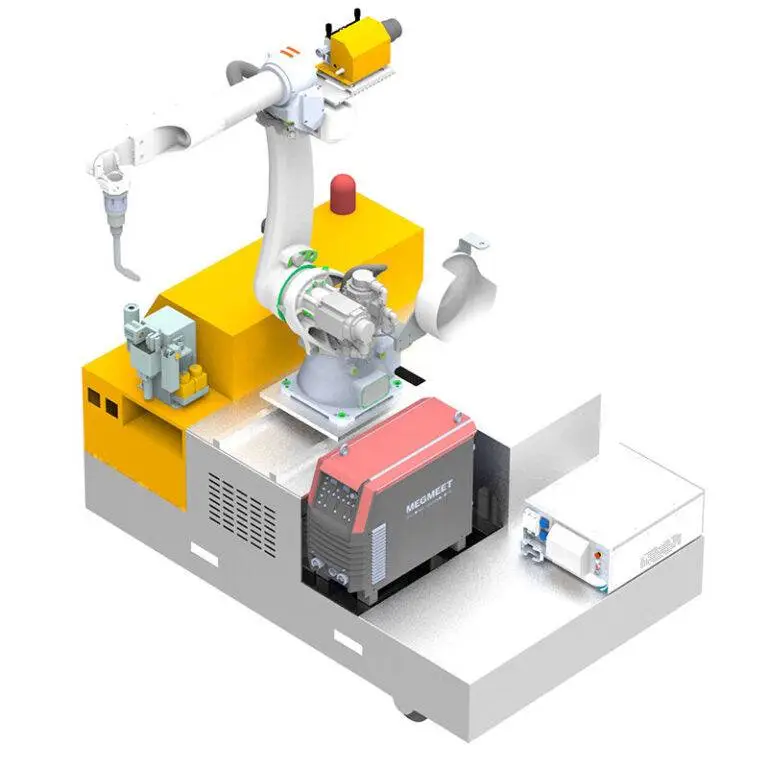
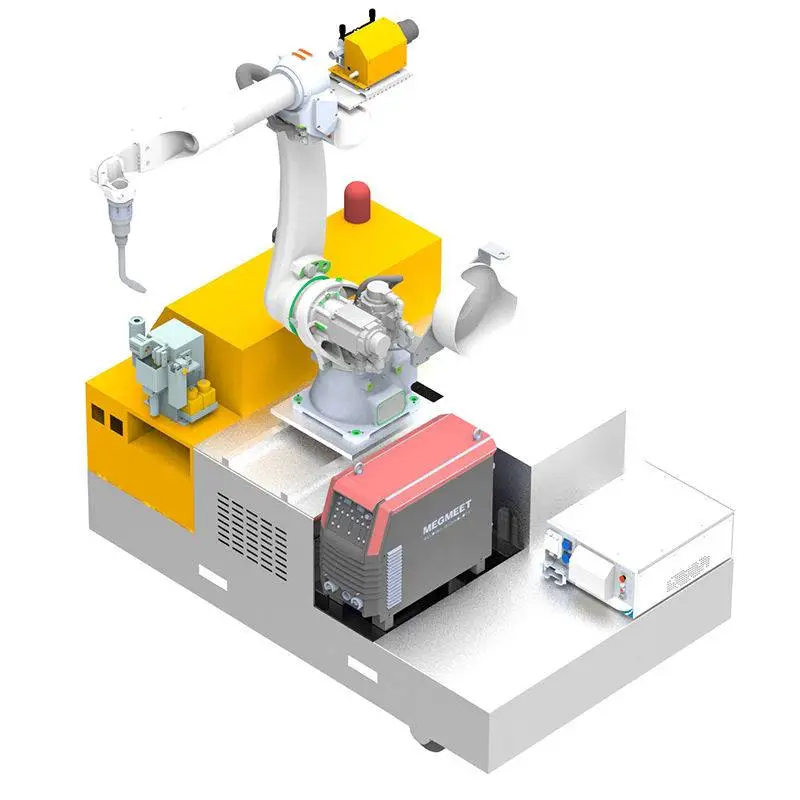
The cell consists of a 6-axis articulated arm mounted on a linear track to service two separate welding stations. This “A/B” station configuration allows for simultaneous loading/unloading and welding.
1. Primary Power Source: 400A Digital Pulse Inverter.
2. Wire Feed: High-speed “Push-Pull” torch system to prevent soft copper wire from bird-nesting.
3. Sensing: Through-arc seam tracking (TAST) to compensate for minor jigging variations.
Practical Implementation on the Shop Floor
During the initial week of deployment in Dusseldorf, we observed a 40% reduction in cycle time compared to the previous semi-automated setups. The primary gain was not just the travel speed, but the elimination of post-weld despatter operations. The precision of the Automated MAG Welding Cell produced a virtually spatter-free finish, which is critical for electrical components where loose metallic particles can cause short circuits in the final assembly.
Lessons Learned and Field Adjustments
Technical transitions of this scale rarely occur without friction. The following are the engineering takeaways from the Dusseldorf commissioning phase.
1. Wire Feed Consistency is Paramount
With Copper Components welding, using soft filler wires (like CuSi or CuAl) requires specialized drive rolls. We initially faced intermittent arc instability. The root cause was identified as “micro-slippage” in the wire feeder. Replacing standard V-groove rolls with U-groove polished rolls resolved the friction issue and stabilized the CMT cycle.
Lesson: In an Automated MAG Welding Cell, the mechanical integrity of the wire path is as important as the electronic parameters of the Arc Welding Solutions.
2. Shielding Gas Turbulence
Dusseldorf’s facility has a high-volume HVAC system. We discovered that cross-drafts were occasionally stripping the shielding gas from the nozzle, leading to nitrogen contamination in the copper welds. We implemented “Gas Lens” technology within the MAG torches and increased the pre-flow timer to 1.5 seconds.
Lesson: Automation increases speed, which can mask gas coverage issues until NDT (Non-Destructive Testing) reveals subsurface porosity. Environmental factors must be shielded as rigorously as the arc itself.
3. Tool Center Point (TCP) Calibration
High-speed MAG welding on copper requires an extremely tight arc gap to maintain the CMT effect. We found that after 50 cycles, the thermal expansion of the torch neck was shifting the TCP by 0.8mm. This was enough to move the arc off the root of the joint. We integrated an automated TCP check station that the robot visits every 20 cycles to recalibrate.
Synergistic Outcomes: Quality and ROI
The integration of these Arc Welding Solutions has transformed the Dusseldorf plant’s output. By leveraging the Automated MAG Welding Cell, we have achieved a first-pass yield of 98.4%, up from 82% with manual processes.
Metallurgical Integrity
Cross-sectional macro-etching of the copper joints shows a refined grain structure. The CMT process’s low heat input prevented the usual “over-tempering” of the copper, preserving the mechanical hardness of the busbars. This is a direct result of the precise control afforded by the Automated MAG Welding Cell.
Future Outlook
The success of Copper Components welding in this cell serves as a blueprint for our upcoming expansion in the Munich facility. The primary takeaway is that automation is not a “set and forget” hardware purchase. It is a continuous engineering exercise in balancing the electrical characteristics of the arc with the physical realities of the material being joined.
In Dusseldorf, we have proven that the MAG process, when augmented with CMT and intelligent robotics, is a superior alternative to TIG for high-conductivity applications. We will continue to refine the pulse-shaping parameters to further reduce the consumption of expensive Helium-mix gases.
Conclusion
The deployment in Dusseldorf confirms that the intersection of an Automated MAG Welding Cell and sophisticated Arc Welding Solutions is the only viable path for high-precision Copper Components welding. The technical hurdles of copper—namely heat dissipation and oxidation—are best managed through the rapid-response feedback loops inherent in modern CMT systems. This field report recommends the immediate rollout of similar cell architectures across all heavy-electrical manufacturing divisions.
End of Report.
Author: Senior Welding Engineer, Dusseldorf Site.