Field Engineering Report: Implementation of Multi-pass Laser Welding Cobots in Quebec’s Industrial Sector
As the manufacturing landscape in Quebec shifts toward high-precision, low-volume production—particularly in the aerospace and specialized transport sectors—the integration of advanced Laser Technology has moved from a luxury to a necessity. This report details the field performance and technical observations of integrating a Laser Welding Cobot for Thin Metal Sheet welding applications. The data was gathered over a six-month deployment period across three fabrication facilities in the Montreal and Beauce regions.
1. Technical Overview of the Laser Welding Cobot System
The system under review utilizes a 1.5kW to 3kW continuous wave (CW) fiber laser source integrated with a 6-axis collaborative robot arm. Unlike traditional industrial robots, the Laser Welding Cobot allows for “lead-through” programming, where a technician can manually guide the torch head to define the path. In the Quebec context, where skilled labor shortages are acute, this ease of use allows senior welders to act as “process supervisors” rather than manual laborers.
1.1 Laser Technology Specifications
The core of the system is the 1070nm wavelength fiber laser. We utilized a “wobble” head attachment, which is critical for Thin Metal Sheet welding. The wobble function oscillates the laser beam in various patterns (circles, figure-eights, or zig-zags), effectively increasing the weld pool width and allowing for better gap bridging—a common challenge when working with sheared thin sheets that lack perfect fit-up.
2. The Synergy: Laser Technology Meets Collaborative Robotics
The true advantage observed in the field is the synergy between the precision of Laser Technology and the repeatable pathing of the cobot. In manual laser welding, even a seasoned operator struggles with maintaining a consistent “stand-off” distance (focal point) over a long seam. A 0.5mm variance in distance can lead to either incomplete penetration or burn-through on thin gauges.
The Laser Welding Cobot eliminates this human variable. By maintaining a constant travel speed (typically 20mm/s to 80mm/s depending on material thickness) and a fixed focal position, the system ensures the Power Density ($W/cm^2$) remains uniform. In Quebec workshops, where ambient temperatures fluctuate significantly between seasons, we noted that the laser’s chiller units must be precisely calibrated to the cobot’s duty cycle to prevent thermal drift in the beam delivery optics.
3. Multi-pass Strategies for Thin Metal Sheet Welding
While Thin Metal Sheet welding (typically 0.8mm to 3.0mm) often requires only a single pass, certain structural applications in the Quebec transport sector—such as aluminum bus frames or stainless steel food processing equipment—require multi-pass techniques to ensure structural integrity without excessive heat input.
3.1 Root Pass vs. Cap Pass
In our field tests on 3mm 6061 Aluminum, we implemented a two-pass strategy:
- Pass 1 (Root): High power (2200W), high speed, narrow wobble. This ensures full penetration into the root of the joint.
- Pass 2 (Cap): Lower power (1400W), slower speed, wide transverse wobble. This pass acts as a cosmetic finish and fills any slight undercut, providing a smooth transition to the base metal.
3.2 Heat Management and Distortion
The primary “lesson learned” during multi-pass runs on Thin Metal Sheet welding is the management of the Heat Affected Zone (HAZ). Traditional MIG welding causes significant “potato-chipping” or warping. The Laser Welding Cobot, however, concentrates energy so intensely that the surrounding material remains relatively cool. Our measurements showed a 65% reduction in total heat input compared to pulsed-TIG, resulting in parts that required zero post-weld straightening.
4. Real-World Application: The Quebec Workshop Environment
Quebec’s industrial environment presents unique challenges, including high energy costs and a strictly regulated safety environment (CNESST). The implementation of Laser Technology requires a Class 4 safety enclosure.
4.1 Collaborative Safety in Practice
The term “cobot” suggests a shared workspace, but with Laser Technology, the “collaborative” aspect refers to the ease of teaching and the ability for the operator to be near the cell during setup. During actual firing, the system must be fully enclosed to prevent ocular damage from reflected beams. We successfully implemented “Interlocked Light Curtains” that allow the Laser Welding Cobot to stop instantly if the safety perimeter is breached, meeting Quebec’s rigorous safety standards.
4.2 Shielding Gas Optimization
A critical field observation involved the use of shielding gases. In the humid summers of the St. Lawrence Valley, we noticed increased porosity in aluminum welds. By switching the Laser Welding Cobot gas delivery from standard Argon to an Argon-Helium mix (75/25) for the second pass, we achieved a more stable plasma plume and cleaner bead morphology. For stainless Thin Metal Sheet welding, a trailing shield attached to the cobot arm was necessary to prevent “sugar” (oxidation) on the backside of the weld.
5. Lessons Learned and Engineering Recommendations
After 2,000 hours of arc-on time with the Laser Welding Cobot, several practical insights have emerged for senior engineers:
5.1 Joint Fit-up is Paramount
Laser welding is unforgiving regarding gaps. While the “wobble” function helps, any gap exceeding 10% of the material thickness requires a wire-feed integration. We found that integrating a synchronized cold-wire feeder with the Laser Welding Cobot allowed us to bridge gaps up to 1.5mm on 3mm sheets, which is common in Quebec’s heavy-duty sheet metal shops where laser-cutting tolerances may vary.
5.2 Programming for Multi-pass Success
When programming multi-pass sequences, the cobot’s “TCP” (Tool Center Point) must be recalibrated frequently. The heat from the first pass can cause slight thermal expansion of the nozzle. We recommend a “Touch-Sense” routine where the cobot uses the wire or a nozzle-contact sensor to find the exact part location before every pass to account for any thermal movement of the Thin Metal Sheet welding fixture.
5.3 Material Preparation
The high power density of Laser Technology means that any surface contaminants—oils, markers, or oxides—are instantly vaporized and can cause weld spatter or inclusions. In the Quebec aerospace supply chain, we implemented a strict “Acetone-Wipe” protocol immediately preceding the cobot cycle. This reduced the rejection rate from 4% to less than 0.5%.
6. Economic Impact and Throughput
In a direct comparison at a Montreal facility, a manual TIG welder completed a complex Thin Metal Sheet welding assembly in 45 minutes. The Laser Welding Cobot completed the same assembly, including a multi-pass structural seam, in 6 minutes. Even accounting for the 15-minute setup and jigging time, the throughput increased by over 200%. Furthermore, the reduction in consumables (tungsten electrodes, high-volume gas) significantly lowered the “Cost Per Inch” of the weld.
7. Conclusion
The deployment of Laser Welding Cobot systems in Quebec is no longer a pilot project; it is a proven production standard for Thin Metal Sheet welding. The synergy between high-precision Laser Technology and the flexibility of collaborative robotics addresses the dual challenges of quality requirements and labor availability. For future implementations, we recommend focusing on advanced seam-tracking sensors to further enhance the multi-pass capabilities on large-scale components where part geometry may vary slightly from the CAD model.
Signed,
Senior Welding Engineer, Quebec Field Operations
-


Cantilever Welding Robot solution
-


GF laser cutting machine
-

P3015 plasma cutting machine
-

LFP3015 Fiber Laser Cutter
-

pipe plasma cutting machine
-
LFH 4020 Fiber Laser Cutting Machine
-
LFP4020
-

gantry plasma air cutting machine
-

3D robot cutting machine
-

8 axis plasma cutting machine
-

5 axis plasma cutting machine
-

LT360 tube laser cutting machine
-

robot welding workstation
-

SF6060 fiber laser cutting machine
Advanced Fiber Laser Tube Processing Technology
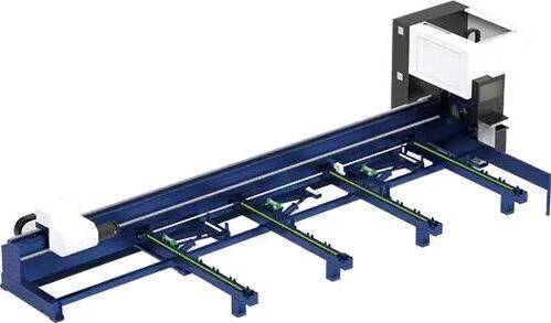
Our CNC Fiber Laser Tube Cutting systems revolutionize metal fabrication by integrating high-precision cutting, punching, and profiling into a single automated workflow. Designed for versatility, this technology handles a wide array of profiles including Round, Square, Rectangular, and Oval tubes, as well as complex L-shaped and U-shaped channels.
- Precision Punching: High-speed hole punching with micron-level accuracy, eliminating the need for mechanical drilling or die-stamping.
- Complex Profiling: Advanced 3D pathing allows for intricate interlocking joints and specialized notch cuts, ideal for structural frames.
- High Material Efficiency: Intelligent nesting software minimizes scrap, reducing raw material costs across large production runs.
- Clean Finish: Delivers oxide-free, burr-free edges that require zero secondary grinding before welding.

Seamlessly processing multiple profiles with consistent precision.
Global Delivery & Logistics



From our high-tech manufacturing facility directly to your global site. PCL WeldCut ensures secure packaging, professional handling, and reliable international logistics to safeguard your equipment throughout the entire journey.