Field Report: Optimization of Multi-pass Automated MAG Welding Cell for High-Conductivity Copper Components
Site Overview: Bologna Heavy Industry Cluster
The following report details the technical commissioning and process optimization of a newly installed Automated MAG Welding Cell located at a Tier-1 industrial manufacturing facility in Bologna, Italy. This region, renowned for precision engineering, requires a high standard of weld integrity, particularly for power distribution assemblies. The project focus was the implementation of multi-pass Copper Components welding using advanced Arc Welding Solutions to replace manual TIG processes that were no longer meeting throughput requirements or consistency benchmarks.
The transition from manual to automated MAG (Metal Active Gas) for copper-heavy assemblies presents significant metallurgical challenges. Copper’s high thermal conductivity (approximately 400 W/m·K) acts as a massive heat sink, often leading to lack-of-fusion defects if the arc energy is not precisely managed. Our objective in Bologna was to synchronize the robotic motion with a specific pulse-on-pulse waveform to ensure deep penetration while maintaining a stable weld pool.
1. Infrastructure: The Automated MAG Welding Cell Configuration
The Automated MAG Welding Cell integrated for this project consists of a six-axis industrial robot mounted on a linear track, paired with a two-axis head-and-tailstock positioner. The choice of a MAG-based system over TIG was driven strictly by the need for high deposition rates in multi-pass applications. In the Bologna workshop, we encountered a specific challenge regarding the duty cycle; the high current required for copper meant that standard air-cooled torches were insufficient. We upgraded the cell to a heavy-duty liquid-cooled system capable of sustaining 500A at 100% duty cycle.
Wire Feed and Gas Management
To ensure consistency, the wire drive system was moved as close to the torch as possible (push-pull configuration). For Copper Components welding, we utilized a 1.2mm diameter deoxidized copper filler wire (ERCu). The shielding gas selection was critical. While pure Argon is standard, we found that a 75% Helium / 25% Argon mix provided the necessary ionization potential to widen the arc cone, facilitating better side-wall fusion in the deep-groove geometries typical of these components.
2. Technical Integration: Synergistic Arc Welding Solutions
The success of this installation relied on the synergy between the physical hardware of the Automated MAG Welding Cell and the digital Arc Welding Solutions implemented via the power source’s software. In the context of the Bologna site, “Arc Welding Solutions” refers to the customized pulse-waveforms designed to overcome the “cold start” phenomenon inherent in copper welding.
Waveform Modulation
Standard CV (Constant Voltage) welding results in excessive spatter and inconsistent penetration on copper due to the rapid dissipation of heat. We utilized a “Power Mode” software suite that adjusts the current in real-time based on the arc length. This ensured that even as the copper component reached high interpass temperatures, the arc remained constricted and focused. The synergy here is clear: the robot (The Cell) provides the geometric precision, while the software (The Solution) manages the physics of the melt pool.
3. Process Deep-Dive: Multi-pass Copper Components Welding
The primary workpieces in the Bologna plant are heavy-duty busbars and induction heating plates. These parts require a multi-pass approach—typically a root pass followed by four to six filler passes and a final cap. Copper Components welding in a multi-pass scenario is notoriously difficult because each subsequent pass changes the thermal profile of the base metal.
The Pre-heat Strategy
Lesson learned: Do not rely solely on the arc for pre-heating. Despite the high-power Arc Welding Solutions, we integrated an automated induction pre-heating station within the cell. We maintained a constant pre-heat of 200°C. This allowed us to lower the welding current slightly, which reduced the risk of grain coarsening in the Heat Affected Zone (HAZ).
Interpass Temperature Control
In Bologna, we implemented an infrared pyrometer linked directly to the Automated MAG Welding Cell controller. If the interpass temperature exceeded 350°C, the robot would trigger a programmed dwell time to prevent “burn-through” or excessive fluidity of the puddle. This level of automation is what separates modern arc welding from traditional methods; it removes the “guesswork” of the operator.
4. Field Challenges and Practical Solutions
No field deployment is without friction. During the first week in Bologna, we struggled with porosity in the root pass. Initially, we suspected gas coverage, but the root cause was the oxide layer on the copper components. Copper oxides have a higher melting point than the base metal and act as a contaminant.
The Solution: Mechanical Preparation and Plasma Cleaning
We modified the workflow to include a mechanical “bright metal” cleaning step immediately before the component entered the Automated MAG Welding Cell. Furthermore, we adjusted the Arc Welding Solutions to include a “cleaning pulse” at the start of the sequence—a high-frequency current burst that breaks down residual oxides. This immediately reduced our NDT (Non-Destructive Testing) failure rate from 12% to less than 0.5%.
Distortion Management
Copper’s high coefficient of thermal expansion leads to significant distortion. By utilizing the Automated MAG Welding Cell‘s ability to perform “back-step” welding sequences and alternating sides of the joint, we were able to keep the dimensional tolerances within the required ±0.5mm. Manual welding could never achieve this level of repeatability due to the physical fatigue of the welder managing such high heat loads.
5. Lessons Learned and Engineering Recommendations
Reflecting on the Bologna installation, several key takeaways should be applied to future Arc Welding Solutions involving non-ferrous metals:
- Data Logging is Mandatory: The Automated MAG Welding Cell was configured to log every weld parameter (voltage, current, gas flow, travel speed). This data was invaluable when troubleshooting the initial porosity issues. If you aren’t logging, you’re just guessing.
- Wire Path Integrity: Copper wire is softer than steel. The conduit liners must be Teflon or graphite-based to prevent “bird-nesting” at the drive rolls. We learned that even a slight kink in the liner would cause arc instability that the software couldn’t compensate for.
- Human-Machine Interface (HMI): While the cell is automated, the local operators in Bologna needed a simplified HMI. We programmed “Job Modes” that allowed them to select material thickness rather than adjusting raw parameters. This minimized human error during changeovers.
Conclusion
The integration of the Automated MAG Welding Cell in Bologna has successfully transitioned the facility from a bottlenecked manual process to a high-efficiency automated line. The marriage of advanced Arc Welding Solutions with the specific requirements of Copper Components welding has proven that even the most thermally challenging materials can be handled with high precision. The key is not just the robot, but the underlying control over the arc physics and the rigorous management of thermal input.
Future iterations will look into integrating seam-tracking sensors to account for the slight thermal warping that occurs during the third and fourth passes. However, as it stands, the cell is exceeding the projected ROI and meeting all ISO 5817 Level B quality standards for heavy industrial applications.
Report Signed:
Senior Welding Engineer
Field Operations – Bologna Site
-


LT240S tube laser cutting machine
-
LT120S tube laser cutting machine
-
Sale

Tank Fillet Welding Machine
Original price was: $1,000.00.$900.00Current price is: $900.00. -
Sale

MAK100 tube laser cutting machine
Original price was: $5,500.00.$5,000.00Current price is: $5,000.00. -

portable plasma air cutting machine
$1,200.00 -

2in1 fiber laser cutting machine
-

Air cooling Laser welding machine
-

HF h beam laser cutting machine
-

LT240 laser cutting machine
-

Laser welding machine
-


Cobot Welding Station
-

Gantry welding robot solution
-

Tracked Wheeled AGV Welding robot
-

LFH6020 Fiber laser cutting machine
-
LFP6020
-

robotic welidng machine
Advanced Fiber Laser Tube Processing Technology
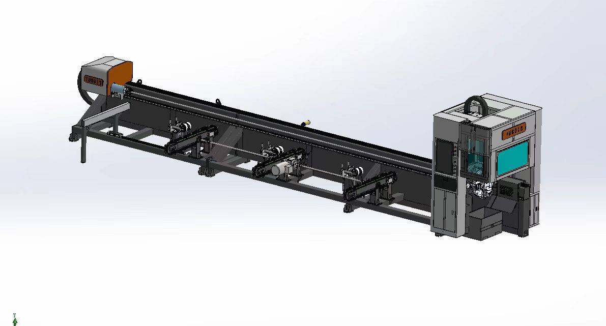
Our CNC Fiber Laser Tube Cutting systems revolutionize metal fabrication by integrating high-precision cutting, punching, and profiling into a single automated workflow. Designed for versatility, this technology handles a wide array of profiles including Round, Square, Rectangular, and Oval tubes, as well as complex L-shaped and U-shaped channels.
- Precision Punching: High-speed hole punching with micron-level accuracy, eliminating the need for mechanical drilling or die-stamping.
- Complex Profiling: Advanced 3D pathing allows for intricate interlocking joints and specialized notch cuts, ideal for structural frames.
- High Material Efficiency: Intelligent nesting software minimizes scrap, reducing raw material costs across large production runs.
- Clean Finish: Delivers oxide-free, burr-free edges that require zero secondary grinding before welding.

Seamlessly processing multiple profiles with consistent precision.
Global Delivery & Logistics



From our high-tech manufacturing facility directly to your global site. PCL WeldCut ensures secure packaging, professional handling, and reliable international logistics to safeguard your equipment throughout the entire journey.
One thought on “Engineering Review: Multi-pass Welding Automated MAG Welding Cell – Bologna, Italy”
The nesting software is very intuitive. Saved us a lot of alloy waste.