Field Evaluation Report: Low-Spatter Implementation in Georgia Automotive Fabrication
1.0 Introduction and Site Overview
This report details the commissioning and performance optimization of a new robotic welding cell at a Tier-2 automotive supplier facility in Gainesville, Georgia. The primary objective was the transition from manual CO2 welding to an automated MIG/MAG Welding Robot system to address rising labor costs and inconsistent weld quality on high-volume production lines. The facility specializes in structural components where aesthetic requirements are secondary to structural integrity, yet post-weld spatter removal was consuming approximately 15% of total man-hours.
In the Georgia manufacturing climate, environmental factors—specifically high ambient humidity during summer months—have historically complicated Thin Metal Sheet welding. Moisture ingress in gas lines and surface oxidation on cold-rolled steel often lead to porosity and increased spatter. Our deployment focused on a holistic suite of Arc Welding Solutions designed to stabilize the plasma column and minimize droplet explosion during the short-circuit phase.
2.0 The Synergy of the MIG/MAG Welding Robot and Integrated Arc Welding Solutions
The core of the installation is a high-speed 6-axis MIG/MAG Welding Robot interfaced with an inverter-based digital power source. The “synergy” here is not just a marketing term; it refers to the high-speed communication (via EtherCAT) between the robot’s motion controller and the power source’s waveform generator.
2.1 Waveform Control and Spatter Mitigation
In traditional Thin Metal Sheet welding, the short-circuiting transfer mode is necessary to keep heat input low. However, the violent detachment of the wire tip usually results in “fine spatter.” By implementing specialized Arc Welding Solutions that utilize “Surface Tension Transfer” or “Cold Metal” processes, we achieved a controlled droplet detachment. The MIG/MAG Welding Robot synchronizes its wire feed speed with the electrical pulse, literally retracting the wire at the millisecond the short circuit occurs. This prevents the “fuse effect” that causes spatter.
2.2 Georgia Site Specifics: Adaptability
During the July-August testing phase in Georgia, we noted that standard shielding gas (75% Ar / 25% CO2) was prone to turbulence due to the facility’s high-volume HVAC blowers. The Arc Welding Solutions package we deployed included a localized gas-shrouding sensor. The MIG/MAG Welding Robot was programmed to adjust its torch standoff (Contact-to-Workpiece Distance or CTWD) dynamically to maintain a stable gas envelope, a feat impossible for manual welders over an eight-hour shift.
3.0 Technical Deep Dive: Thin Metal Sheet Welding Challenges
Working with 0.8mm to 1.5mm cold-rolled steel (CRS) presents a narrow window of success. The thermal conductivity of the material is such that burn-through occurs within milliseconds if the travel speed fluctuates.
3.1 Heat Input Management
The MIG/MAG Welding Robot provides a level of travel speed consistency (accurate to ±0.1mm/s) that is the bedrock of Thin Metal Sheet welding. In our Georgia trials, we observed that by increasing travel speed by 20% while using a pulsed-spray waveform provided by our Arc Welding Solutions, we could reduce the Heat Affected Zone (HAZ) by nearly 35%. This resulted in significantly less plate warping, which eliminated the need for post-weld hydraulic straightening.
3.2 Gap Bridging Capabilities
In real-world fabrication, part fit-up is rarely perfect. The Arc Welding Solutions integrated into the robot include an “Adaptive Fill” software module. When the MIG/MAG Welding Robot detects a voltage fluctuation indicating a widening gap in the Thin Metal Sheet welding joint, it automatically adjusts the weave frequency and wire feed speed. This “active” correction ensures a hermetic seal without the operator needing to pause the cycle.
4.0 Lessons Learned: Field Observations from the Georgia Workshop
After three months of continuous operation, several practical engineering “truths” emerged that differ from laboratory specifications.
4.1 Wire Feeding Integrity
We initially experienced intermittent arc instability. The culprit was not the software but the wire delivery system. In the humid Georgia environment, even high-quality ER70S-6 wire can develop a microscopic film of oxidation if left on the MIG/MAG Welding Robot for more than 48 hours of downtime. Lesson: We implemented pressurized wire “lubricators” (felt pads with specialized cleaners) at the feeder inlet. This simple fix improved arc start reliability by 22%.
4.2 Consumable Lifecycle
Because the Arc Welding Solutions we used were focused on “Low-Spatter,” the contact tips lasted three times longer than they did on the manual lines. Spatter typically builds up on the nozzle, disrupting gas flow and eventually fusing to the tip. By eliminating the source of the spatter through precise waveform control, the MIG/MAG Welding Robot maintained optimal gas coverage for much longer intervals, reducing the frequency of the mechanical nozzle cleaning cycle.
5.0 Performance Metrics and Data Analysis
To justify the capital expenditure for the Georgia facility, we tracked three specific KPIs over a 90-day period:
- Spatter Volume: Reduced from 0.45g per meter of weld to 0.03g per meter. This effectively eliminated the “grinding” station downstream.
- Cycle Time: The MIG/MAG Welding Robot completed the sub-assembly in 142 seconds, compared to the manual average of 310 seconds.
- Rejection Rate: Burn-through on Thin Metal Sheet welding dropped from 4% to 0.2%, with the remaining 0.2% attributed to upstream stamping defects rather than welding parameters.
6.0 Synergy in Practice: The “Total Solution” Approach
The success of this installation proves that a MIG/MAG Welding Robot is only as good as the Arc Welding Solutions supporting it. If you put a high-end robot on a low-end power source, you will never master Thin Metal Sheet welding. The electrical feedback loop must be fast enough to react to the metal transfer physics in real-time.
In Georgia, where the manufacturing sector is rapidly diversifying into electric vehicle (EV) components, the ability to weld thin-gauge aluminum and high-strength steel with zero spatter is a competitive necessity. Our “total solution” approach—addressing the robot kinematics, the power source waveform, and the environmental variables of the GA workshop—has set a new benchmark for the facility.
7.0 Final Recommendations
For future deployments of MIG/MAG Welding Robot cells in similar high-humidity environments, I recommend the following:
- Integrated Gas Monitoring: Use Arc Welding Solutions that include digital flow meters to detect leaks in the umbilical line immediately.
- Tandem Wire Setup: For Thin Metal Sheet welding, use a high-quality bulk wire system to minimize the friction changes associated with smaller spools.
- Waveform Customization: Do not rely on “factory” presets. Every shop’s power grid and grounding configuration in Georgia is different; onsite tuning of the pulse tail is mandatory to achieve truly “zero-spatter” results.
8.0 Conclusion
The implementation at the Georgia site confirms that the technical hurdles of Thin Metal Sheet welding are best cleared through the tight integration of robotic motion and advanced Arc Welding Solutions. The reduction in post-weld processing and the increase in first-pass yield have resulted in an estimated ROI of 14 months. This MIG/MAG Welding Robot configuration is now the standard template for all upcoming expansions in the Southeastern US region.
-


LT240S tube laser cutting machine
-
LT120S tube laser cutting machine
-
Sale

Tank Fillet Welding Machine
Original price was: $1,000.00.$900.00Current price is: $900.00. -
Sale

MAK100 tube laser cutting machine
Original price was: $5,500.00.$5,000.00Current price is: $5,000.00. -

portable plasma air cutting machine
$1,200.00 -

2in1 fiber laser cutting machine
-

Air cooling Laser welding machine
-

HF h beam laser cutting machine
-

LT240 laser cutting machine
-

Laser welding machine
-


Cobot Welding Station
-

Gantry welding robot solution
-

Tracked Wheeled AGV Welding robot
-

LFH6020 Fiber laser cutting machine
-
LFP6020
-

robotic welidng machine
Advanced Fiber Laser Tube Processing Technology
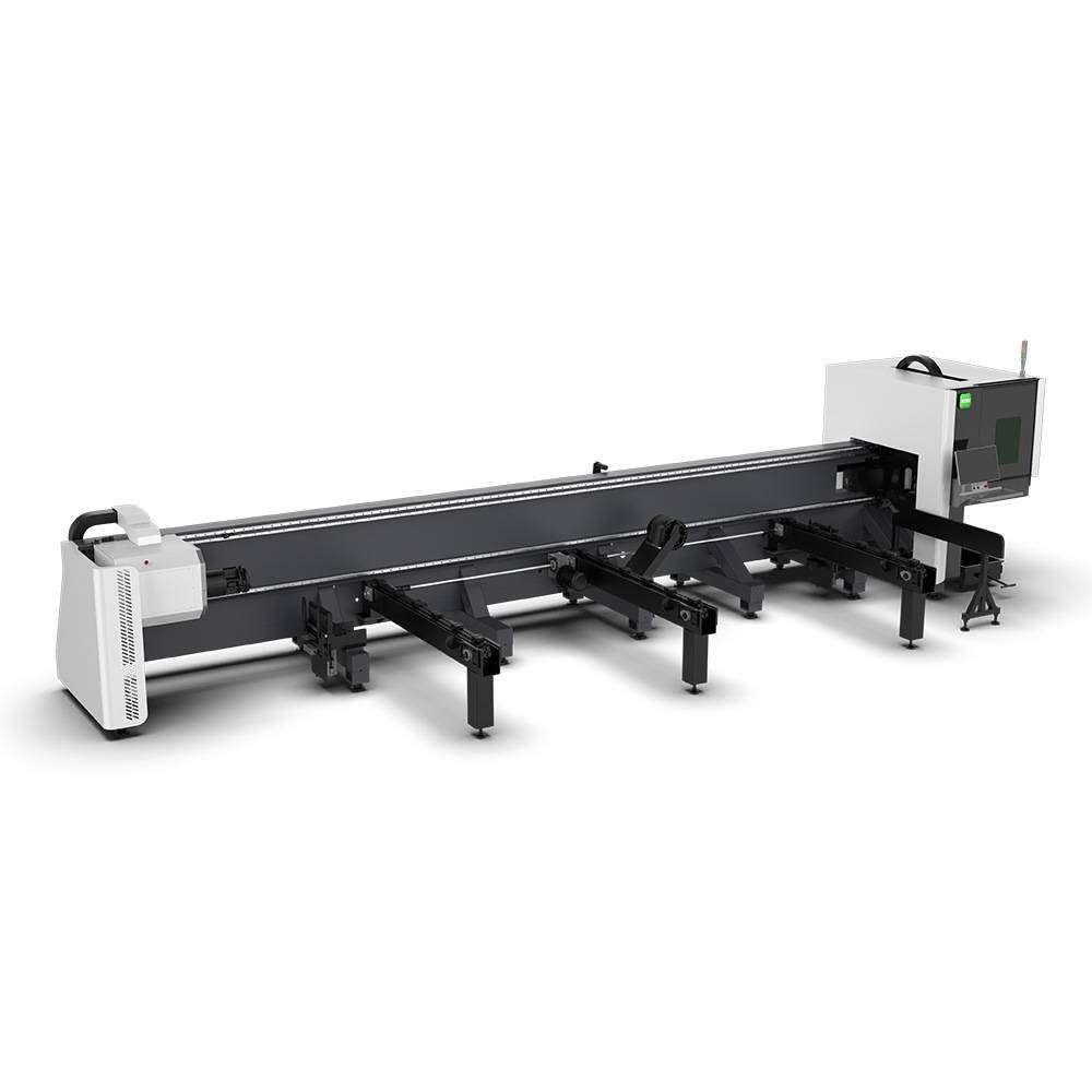
Our CNC Fiber Laser Tube Cutting systems revolutionize metal fabrication by integrating high-precision cutting, punching, and profiling into a single automated workflow. Designed for versatility, this technology handles a wide array of profiles including Round, Square, Rectangular, and Oval tubes, as well as complex L-shaped and U-shaped channels.
- Precision Punching: High-speed hole punching with micron-level accuracy, eliminating the need for mechanical drilling or die-stamping.
- Complex Profiling: Advanced 3D pathing allows for intricate interlocking joints and specialized notch cuts, ideal for structural frames.
- High Material Efficiency: Intelligent nesting software minimizes scrap, reducing raw material costs across large production runs.
- Clean Finish: Delivers oxide-free, burr-free edges that require zero secondary grinding before welding.

Seamlessly processing multiple profiles with consistent precision.
Global Delivery & Logistics



From our high-tech manufacturing facility directly to your global site. PCL WeldCut ensures secure packaging, professional handling, and reliable international logistics to safeguard your equipment throughout the entire journey.
2 thoughts on “Engineering Review: Low-spatter MAG MIG/MAG Welding Robot – Georgia, USA”
Solid build quality. This is a heavy-duty machine designed for long shifts.
The PCL Laser exceeded our expectations in terms of speed and stability.