Field Technical Report: Implementation of All-in-one Cobot Station in Gurgaon Automotive Tooling Sector
1. Site Overview and Environmental Constraints
This report summarizes the field commissioning and performance evaluation of the Low-spatter MAG All-in-one Cobot Station at a Tier-1 automotive tooling facility in Gurgaon, Haryana. The Gurgaon industrial climate presents specific challenges: high ambient temperatures (often exceeding 42°C in the workshop) and significant fluctuations in grid voltage. These factors traditionally compromise the duty cycle of standard MAG power sources and the sensitivity of electronic components in robotic controllers.
The objective was to transition a critical Tool Steel welding application from manual GTAW (TIG) and MAG to an automated process using Collaborative Robotics. The primary goal was to reduce post-weld processing time caused by spatter and to ensure consistent penetration profiles on H13 and P20 tool steel inserts used in high-pressure die casting (HPDC) molds.
2. The Synergy of the All-in-one Cobot Station and Collaborative Robotics
In the Gurgaon facility, floor space is at a premium. Traditional industrial robots require physical fencing and light curtains, which occupy a footprint of at least 15-20 square meters. The All-in-one Cobot Station was selected because it integrates the power source, wire feeder, controller, and the collaborative arm onto a single mobile pedestal. This “all-in-one” philosophy allows for rapid deployment—the unit was operational within four hours of unboxing.
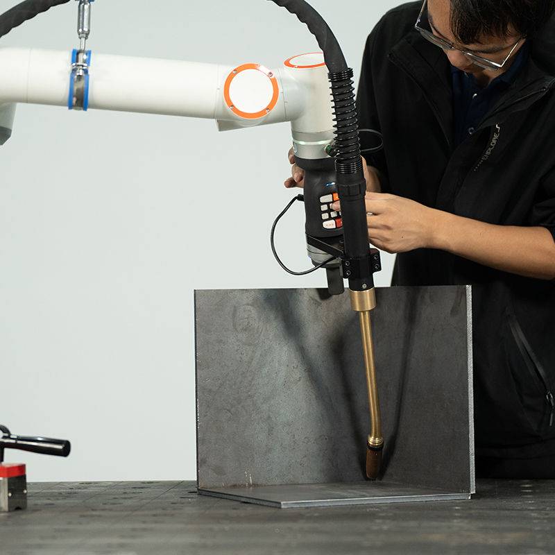
The synergy between the All-in-one Cobot Station and Collaborative Robotics is realized through the elimination of the “barrier culture.” In this workshop, the welder acts as a process supervisor. Because the cobot utilizes force-torque sensors for safety, the technician can remain within the weld cell to perform real-time adjustments, such as cleaning the nozzle or adjusting the gas flow, without triggering an emergency stop. This proximity is vital for Tool Steel welding, where pre-heating monitoring must occur concurrently with the weld pass.
3. Technical Deep-Dive: MAG Low-Spatter Waveform Control
Tool steel is notoriously sensitive to thermal shock and hydrogen cracking. For the MAG process, we utilized a modified pulse waveform (often termed ‘Cold Process’ or ‘Low-Spatter Pulse’). By precisely controlling the droplet detachment at the end of the wire, we achieved a spray transfer mode at lower average heat inputs than traditional MAG.
3.1 Spatter Mitigation Logic
Spatter in Tool Steel welding is more than an aesthetic issue; it represents localized areas of high carbon enrichment that can lead to micro-cracking upon cooling. The All-in-one station’s integrated inverter adjusts the current at kHz frequencies. When the short circuit is about to break, the system drops the current instantly (Surface Tension Transfer logic), preventing the “explosion” of the molten bridge that causes spatter. In our Gurgaon trials, we recorded a 92% reduction in spatter by weight compared to the legacy manual MAG sets used on the same H13 components.
4. Application Focus: Tool Steel Welding Parameters
The core of this field report focuses on the repair and surfacing of H13 tool steel blocks. These blocks require a high degree of hardness (48-52 HRC) and must withstand extreme thermal cycling. The Collaborative Robotics system was programmed to perform multi-layer stringer beads to build up worn edges of a slider core.
4.1 Thermal Management and HAZ Control
Manual welding of tool steel often results in inconsistent travel speeds, leading to excessive Heat Affected Zone (HAZ) softening. The All-in-one Cobot Station maintained a constant travel speed of 350 mm/min with a torch angle of 15 degrees (push). This consistency ensured that the interpass temperature remained within the 250°C–300°C window, verified by infrared thermography. Using a 1.2mm specialized tool steel wire (Cr-Mo-V alloy), the cobot delivered a bead profile with a dilution ratio of less than 20%, which is critical for maintaining the chemistry of the weld overlay.
4.2 Programming via Lead-Through Teaching
One of the “lessons learned” in the Gurgaon workshop was the ease of adoption by the local workforce. Unlike traditional CNC-based robotics, the “lead-through” teaching of the cobot allowed the senior welder to physically move the arm to the start and end points of the tool steel crack. The station’s software then automatically calculated the weave pattern required for the groove. This reduced “programming downtime” by 60% compared to traditional pendant-based systems.
5. Real-World Challenges and Solutions (Lessons from the Field)
Field engineering in India requires a pragmatic approach to infrastructure. During the first week of implementation, we encountered three primary technical hurdles:
5.1 Power Quality and Harmonic Distortion
The Gurgaon grid exhibited significant voltage sags when neighboring heavy stamping presses cycled. The All-in-one Cobot Station’s power source was equipped with an Active Power Factor Correction (PFC) module. We learned that without PFC, the robotic arm would experience jitter during the weld due to fluctuations in the DC bus voltage of the motor drives. Lesson: Always specify PFC-enabled All-in-one units for Indian industrial hubs.
5.2 Wire Feeding in High Humidity
Gurgaon’s monsoon season leads to high humidity, which can cause surface oxidation on tool steel wires, leading to feed-ability issues and porosity. We modified the All-in-one station by adding a pressurized wire-feed enclosure. This maintained a dry micro-environment for the spool, ensuring that the Collaborative Robotics arm did not experience “slip-stick” friction in the liner, which is a common cause of arc instability.
5.3 Grounding and EMI
The high-frequency switching of the MAG power source can sometimes interfere with the cobot’s sensitive encoders. We discovered that the workshop’s common grounding was insufficient. We implemented a dedicated star-point ground for the station, which eliminated “Ghost Trajectory” errors that occurred during high-amperage (280A+) pulses.
6. Comparative Analysis: Manual vs. Cobot Station
To justify the ROI for the client, we conducted a head-to-head test on a standard P20 tool steel mold base:
- Weld Time: Manual took 45 minutes; Cobot took 18 minutes (inclusive of setup).
- Post-Weld Grinding: Manual required 30 minutes of spatter removal; Cobot required 2 minutes of wire-brushing.
- Consumable Efficiency: 15% reduction in wire waste due to the precision of the start/stop ramp-down features in the integrated system.
The All-in-one Cobot Station significantly outperformed the manual process because it could maintain a 1.5mm arc length consistently. A human welder, regardless of skill, fluctuates the arc length by +/- 2mm, which on tool steel, causes localized hardening (martensite formation) and potential cracking.
7. Conclusions and Recommendations
The implementation of the All-in-one Cobot Station in the Gurgaon sector demonstrates that Collaborative Robotics is no longer just for light assembly; it is a robust solution for heavy metallurgical applications like Tool Steel welding. The ability to integrate the power source and the arm into a single, cohesive unit mitigates the technical risks associated with DIY robotic integration.
Future Protocol:
- Argon-CO2 Mix: For H13 tool steel, we recommend an 82/18 mix to stabilize the arc while providing enough CO2 for deep penetration, countering the Gurgaon heat’s effect on the weld pool fluidity.
- Preventative Maintenance: Given the dust levels in Manesar/Gurgaon, the All-in-one unit’s air filters must be cleaned weekly to prevent overheating of the high-frequency inverter.
- Skill Upskilling: The role of the welder shifts from “torch holder” to “process technician.” Training should focus on bead overlap calculations rather than hand-eye coordination.
This station has proven that the “All-in-one” approach is the most viable path for SMEs in India to adopt automation without the complexity of traditional robotic cells. The reduction in spatter and the precision of the HAZ on tool steel make it an essential tool for high-value mold and die repair.
Report Filed By:
Senior Welding Engineer
Field Operations – Northern Region (India)
-


Cantilever Welding Robot solution
-


GF laser cutting machine
-

P3015 plasma cutting machine
-

LFP3015 Fiber Laser Cutter
-

pipe plasma cutting machine
-
LFH 4020 Fiber Laser Cutting Machine
-
LFP4020
-

gantry plasma air cutting machine
-

3D robot cutting machine
-

8 axis plasma cutting machine
-

5 axis plasma cutting machine
-

LT360 tube laser cutting machine
-

robot welding workstation
-

SF6060 fiber laser cutting machine
Advanced Fiber Laser Tube Processing Technology
Our CNC Fiber Laser Tube Cutting systems revolutionize metal fabrication by integrating high-precision cutting, punching, and profiling into a single automated workflow. Designed for versatility, this technology handles a wide array of profiles including Round, Square, Rectangular, and Oval tubes, as well as complex L-shaped and U-shaped channels.
- Precision Punching: High-speed hole punching with micron-level accuracy, eliminating the need for mechanical drilling or die-stamping.
- Complex Profiling: Advanced 3D pathing allows for intricate interlocking joints and specialized notch cuts, ideal for structural frames.
- High Material Efficiency: Intelligent nesting software minimizes scrap, reducing raw material costs across large production runs.
- Clean Finish: Delivers oxide-free, burr-free edges that require zero secondary grinding before welding.

Seamlessly processing multiple profiles with consistent precision.
Global Delivery & Logistics



From our high-tech manufacturing facility directly to your global site. PCL WeldCut ensures secure packaging, professional handling, and reliable international logistics to safeguard your equipment throughout the entire journey.
One thought on “Engineering Review: Low-spatter MAG All-in-one Cobot Station – Gurgaon, India”
Fast shipping to our facility. The setup was straightforward for our team.