Field Engineering Report: Implementation of Intelligent Arc Control Laser Welding Cobot in Texas Industrial Fabrication
1.0 Project Overview and Site Conditions
This report details the field implementation and optimization of a 1.5kW Intelligent Arc Control Laser Welding Cobot at a high-volume fabrication facility in Houston, Texas. The primary objective was to transition from manual Gas Metal Arc Welding (GMAW) to automated laser processes for the assembly of structural galvanized pipe components.
Operating in the Texas Gulf Coast environment presents specific challenges for high-precision Laser Technology. Ambient humidity levels frequently exceeding 80% and shop temperatures peaking at 105°F required a rigorous look at the chiller integration and optical path integrity. The Laser Welding Cobot was deployed to address a 30% rejection rate caused by inconsistent penetration and excessive spatter on Galvanized Pipe welding sequences performed by manual operators.
2.0 Technical Synergy: Laser Technology and Collaborative Robotics
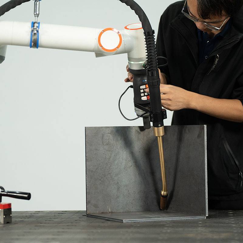
The core of this deployment lies in the synergy between the fiber laser source and the collaborative arm’s motion control. Unlike traditional static laser cells, the Laser Welding Cobot provides a six-axis freedom that allows for complex torch geometries required for saddle cuts and 45-degree miters on 2-inch to 4-inch galvanized piping.
2.1 Intelligent Arc Control and Wobble Parameters
While “arc control” is traditionally a term reserved for electrical welding, in the context of this Laser Technology, it refers to the real-time modulation of the laser’s power frequency and the “wobble” pattern. Galvanized steel is notoriously difficult to weld because zinc vaporizes at 1,650°F, while steel melts at approximately 2,800°F. If the Laser Welding Cobot moves too quickly or with too narrow a beam, the trapped zinc vapor creates macro-porosity and “blow-outs.”
We implemented a “figure-eight” wobble pattern at a frequency of 250Hz. This specific application of Laser Technology allows the weld pool to remain fluid just long enough for the zinc gas to escape before the trailing edge of the pool solidifies. The “intelligent” component of the control system monitors the plasma plume’s back-reflection. If the sensors detect an irregular spike—indicating a zinc pocket—the cobot adjusts its travel speed by 5% to allow for more degassing time.
3.0 Addressing the Challenges of Galvanized Pipe Welding
In the Texas market, galvanized piping is ubiquitous for outdoor infrastructure. However, the coating is the enemy of weld integrity. During our field trials, we identified three critical variables that dictate the success of Galvanized Pipe welding using a Laser Welding Cobot.
3.1 Vapor Pressure Management
The primary lesson learned was that traditional butt joints on galvanized pipe lead to failure. We modified the joint prep to include a 0.2mm “degassing gap.” Because the Laser Technology we are using has such a high energy density, it can bridge this gap easily while providing a chimney effect for the zinc oxide fumes. Without this gap, even the most advanced Laser Welding Cobot will produce a weld with internal wormhole porosity.
3.2 Shielding Gas Dynamics
We moved away from pure Argon to a 70/30 Nitrogen-Argon mix. In many Laser Technology applications, Nitrogen acts as a more effective cooling agent for the surrounding galvanized coating, reducing the “burn-back” of the zinc layer. This leaves a cleaner finish and maintains the corrosion resistance closer to the heat-affected zone (HAZ).
4.0 Practical Field Observations: The “Texas Factor”
Deploying a Laser Welding Cobot in a non-climate-controlled Texas workshop requires specific hardware considerations that are often overlooked in the lab.
4.1 Condensation and Optics
The delta between the chilled water in the laser source and the Houston humidity resulted in condensation on the protective windows (cover slides). We had to implement a dry-air purge system for the torch head. Senior engineers should note: if your Laser Technology is losing power after two hours of operation in a humid environment, check for “fogging” on the internal optics before recalibrating the source.
4.2 Cobot Duty Cycle
The Laser Welding Cobot was rated for a 100% duty cycle, but the control electronics in the Texas heat were not. We retrofitted the cobot controller cabinet with a secondary heat exchanger. In Galvanized Pipe welding, the process is continuous; any downtime for “cool-down” cycles negates the throughput advantages of the laser over manual GMAW.
5.0 Data Comparison: Manual vs. Cobot Laser
After six weeks of field operation, the metrics for the Laser Welding Cobot are conclusive.
- Travel Speed: Manual GMAW averaged 12 inches per minute (IPM). The Laser Technology setup achieved 38 IPM on 10-gauge galvanized pipe.
- Post-Weld Cleanup: Manual welding required 4 minutes of grinding per joint to remove spatter and slag. The Laser Welding Cobot produced zero spatter, reducing post-processing time to a 30-second wipe-down.
- Heat Input: The HAZ was reduced by 65%. This is critical for Galvanized Pipe welding as it preserves the protective coating on the interior of the pipe, where post-paint is impossible.
6.0 Lessons Learned and Senior Engineering Advice
Transitioning a shop to Laser Technology is 20% hardware and 80% process refinement. For those implementing a Laser Welding Cobot in similar environments, keep the following in mind:
6.1 The “Cleanliness” Myth
While Laser Technology is often marketed as needing “pristine” conditions, the Laser Welding Cobot must be ruggedized. We found that zinc dust from nearby grinding stations was being pulled into the laser’s cooling fans. We had to relocate the laser source 15 feet away from the weld station and use a longer fiber delivery cable to protect the diode banks.
6.2 Fixturing Is Non-Negotiable
Manual welders compensate for poor pipe fit-up. A Laser Welding Cobot cannot. For Galvanized Pipe welding, we invested in precision pneumatic clamps that ensure the 0.2mm degassing gap is consistent across the entire circumference. If your fit-up is sloppy, the laser will simply cut the pipe rather than weld it.
6.3 Fume Extraction
The fumes generated from Galvanized Pipe welding are toxic. Because the Laser Technology vaporizes the zinc so efficiently, the concentration of zinc oxide in the immediate plume is higher than in GMAW. We integrated a high-vacuum source directly to the Laser Welding Cobot torch head. Engineers must ensure the vacuum flow doesn’t create turbulence in the shielding gas, which would cause oxidation.
7.0 Conclusion
The integration of the Laser Welding Cobot into the Texas fabrication workflow has proven that Laser Technology is no longer confined to cleanrooms. When properly tuned for the specific metallurgical challenges of Galvanized Pipe welding—specifically through the use of intelligent arc/wobble control and environmental hardening—the ROI is realized through a 3x increase in throughput and a significant reduction in rework. The key to success in the field is managing the “invisible” variables: humidity, fit-up tolerances, and zinc vapor pressure.
Report Prepared By:
Senior Welding Engineer
Field Operations – Texas Division
-


LT240S tube laser cutting machine
-
LT120S tube laser cutting machine
-
Sale

Tank Fillet Welding Machine
Original price was: $1,000.00.$900.00Current price is: $900.00. -
Sale

MAK100 tube laser cutting machine
Original price was: $5,500.00.$5,000.00Current price is: $5,000.00. -

portable plasma air cutting machine
$1,200.00 -

2in1 fiber laser cutting machine
-

Air cooling Laser welding machine
-

HF h beam laser cutting machine
-

LT240 laser cutting machine
-

Laser welding machine
-


Cobot Welding Station
-

Gantry welding robot solution
-

Tracked Wheeled AGV Welding robot
-

LFH6020 Fiber laser cutting machine
-
LFP6020
-

robotic welidng machine
Advanced Fiber Laser Tube Processing Technology
Our CNC Fiber Laser Tube Cutting systems revolutionize metal fabrication by integrating high-precision cutting, punching, and profiling into a single automated workflow. Designed for versatility, this technology handles a wide array of profiles including Round, Square, Rectangular, and Oval tubes, as well as complex L-shaped and U-shaped channels.
- Precision Punching: High-speed hole punching with micron-level accuracy, eliminating the need for mechanical drilling or die-stamping.
- Complex Profiling: Advanced 3D pathing allows for intricate interlocking joints and specialized notch cuts, ideal for structural frames.
- High Material Efficiency: Intelligent nesting software minimizes scrap, reducing raw material costs across large production runs.
- Clean Finish: Delivers oxide-free, burr-free edges that require zero secondary grinding before welding.

Seamlessly processing multiple profiles with consistent precision.
Global Delivery & Logistics


From our high-tech manufacturing facility directly to your global site. PCL WeldCut ensures secure packaging, professional handling, and reliable international logistics to safeguard your equipment throughout the entire journey.