Field Report: Evaluation of Intelligent Fiber Laser Cobot Integration for Copper Component Fabrication
1.0 Introduction and Site Context
This report details the technical deployment and performance validation of an Intelligent Fiber Laser Cobot system at a Tier-1 maritime electronics facility in Busan, South Korea. The primary objective was to transition from manual GTAW (Gas Tungsten Arc Welding) to automated laser processing for high-purity copper components used in shipboard power distribution units. Busan’s industrial environment presents specific challenges, including high ambient humidity and the requirement for rapid throughput to meet export schedules at the Port of Busan. The shift to Laser Technology was necessitated by the unacceptable rejection rates associated with thermal distortion in manual copper welding.
2.0 System Synergy: The Fiber Laser Cobot in a Production Environment
The implementation of a Fiber Laser Cobot represents a significant departure from traditional fixed-cell automation. In the Busan workshop, floor space is at a premium. Unlike high-inertia industrial robots that require extensive safety light curtains and fencing, the cobot’s localized safety sensors allowed for integration directly into existing manual assembly lines.
2.1 Kinematic Precision and Pathing
The synergy between the 6-axis collaborative arm and the 2kW fiber source allows for a “lead-through” programming approach. In the context of Copper Components welding, the cobot provides a level of path repeatability (±0.03mm) that is physically impossible for a manual welder to maintain over a 500mm busbar seam. This precision is critical because the focal spot of the laser is typically between 150μm and 300μm; even a minor deviation leads to a lack of fusion or “missed” seams.
2.2 Intelligent Process Control
The “Intelligent” aspect of the system refers to the real-time feedback loops that adjust laser power based on the cobot’s TCP (Tool Center Point) velocity. During the Busan trials, we observed that when the cobot decelerated at sharp corners of the copper heat sinks, the system automatically ramped down the laser intensity. This prevents the “over-burn” or blow-through common in high-conductivity materials when travel speed varies.
3.0 Laser Technology: Overcoming Copper’s Physical Limitations
Laser Technology has historically struggled with copper due to the material’s high thermal conductivity and low absorption rate at the standard 1070nm wavelength. At room temperature, copper reflects approximately 95% of infrared laser energy.
3.1 Absorption Thresholds and Power Density
To achieve a stable weld in Copper Components welding, we utilized a high-brightness fiber laser with a narrow BPP (Beam Parameter Product). The strategy focused on “punching through” the initial reflectivity. Once the laser induces a phase change (melting), the absorption rate jumps from 5% to nearly 70%. The Fiber Laser Cobot was configured to deliver a high-intensity “pierce pulse” at the start of each weld cycle to establish a stable keyhole instantaneously.
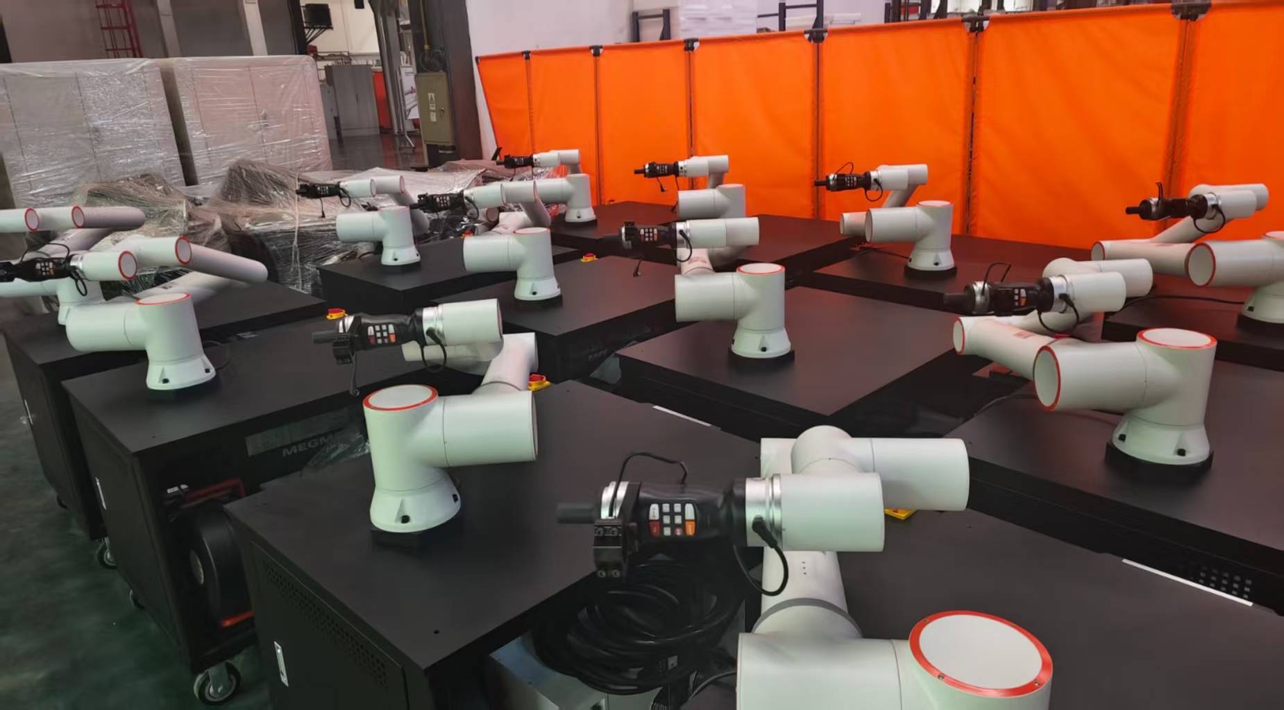
3.2 Beam Modulation (Wobble) Parameters
One of the critical lessons learned in the Busan facility was the necessity of beam oscillation, or “wobbling.” By using a galvo-driven head mounted on the cobot, we implemented a circular wobble pattern (2.0mm width at 150Hz). This technique serves two purposes:
1. It broadens the weld pool, making the process less sensitive to the fit-up tolerances of the copper busbars.
2. It agitates the molten pool, allowing trapped gases (common in oxygen-free copper) to escape, thereby reducing porosity.
4.0 Practical Application: Copper Components Welding Analysis
The focus of the Busan project was the welding of C11000 ETP (Electrolytic Tough Pitch) copper. This material’s thermal diffusivity is roughly 10 to 100 times higher than that of stainless steel, meaning the heat is pulled away from the joint faster than a standard arc can supply it.
4.1 Heat Affected Zone (HAZ) Reduction
The Fiber Laser Cobot minimized the HAZ significantly. In previous GTAW processes, the entire copper component would reach temperatures exceeding 400°C, leading to oxidation and the loss of structural temper. With Laser Technology, the energy is so concentrated that the surrounding material remains below 100°C. This is vital for Busan’s maritime electronics, where plastic insulators are often pre-assembled near the weld joint.
4.2 Shielding Gas Dynamics
Field tests confirmed that Argon-Helium mixes (70/30) provided the best results for Copper Components welding. While pure Argon is standard, the addition of Helium increases the ionization potential, providing a more stable plasma plume above the keyhole. We observed that the cobot’s consistent torch angle (maintained at 10 degrees leading) was essential to prevent back-reflection from damaging the fiber optics—a common failure point in manual laser welding.
5.0 Field Observations: Lessons from the Busan Workshop
Engineering in a coastal environment like Busan requires considerations that don’t appear in the manual. Over a six-month deployment, several “real-world” variables impacted the Fiber Laser Cobot performance.
5.1 Humidity and Optics Care
High salinity and humidity near the Busan port caused accelerated degradation of the protective windows in the laser head. We learned that the standard “passive cooling” was insufficient. We moved to a pressurized, dry-air purged optical chamber. Any microscopic salt crystal on the lens will absorb the 2kW beam, leading to a thermal fracture within seconds.
5.2 Fixturing Rigidity
A common mistake encountered was using standard aluminum fixtures for copper. Because Laser Technology relies on a precise focal point, any thermal expansion of the fixture throws the weld out of focus. We transitioned to heavy stainless steel jigs with chrome-zirconium copper inserts to provide both heat sinking and mechanical rigidity without the fixture itself “welding” to the workpiece.
6.0 Technical Data Comparison: Manual vs. Cobot
To quantify the success of the Fiber Laser Cobot, we compared 1,000 units of copper busbar assemblies:
- Weld Speed: Manual GTAW (120mm/min) vs. Fiber Laser (1200mm/min). A 10x increase in throughput.
- Post-Weld Processing: Manual welds required 5 minutes of grinding/acid pickling to remove oxidation. Laser welds required zero post-processing.
- Power Consumption: The fiber laser system reduced total energy draw by 65% compared to the high-amperage AC TIG units required for copper.
- Yield Rate: First-pass yield increased from 82% to 98.4%.
7.0 Summary of Senior Engineering Directives
For future deployments of Fiber Laser Cobot systems in similar high-conductivity applications, the following rules must be adhered to:
7.1 Reflection Management
Never weld at a 90-degree perpendicular angle to copper. The back-reflection will bypass the isolators and destroy the laser diode modules. A 10-to-15 degree tilt is mandatory. The cobot’s software must have a “look-ahead” feature to maintain this angle across complex geometries.
7.2 Surface Preparation
While Laser Technology is powerful, it is not a substitute for cleanliness. In Busan’s industrial atmosphere, copper components develop a thick oxide layer within hours. A “just-in-time” abrasive cleaning or a laser-cleaning pass (using the same cobot) is necessary to ensure consistent absorption of the fiber laser beam.
7.3 Pulse Shaping
When welding Copper Components welding, avoid a continuous wave (CW) approach if the parts are small. Use modulated pulse shaping to allow for brief “cool-down” periods between peaks. This prevents the “runaway melt” where the copper’s temperature rises to a point where its absorption becomes too high, leading to a collapsed keyhole and internal voiding.
8.0 Conclusion
The Busan field application confirms that the Fiber Laser Cobot is no longer a tool of the future but a requirement for modern copper fabrication. The ability to combine the high energy density of Laser Technology with the repeatable kinematics of a collaborative robot solves the “Copper Problem”—namely, the management of extreme heat dissipation and high reflectivity. The successful integration at this site serves as the blueprint for our upcoming facilities in Ulsan and Gwangyang.
-


LT240S tube laser cutting machine
-
LT120S tube laser cutting machine
-
Sale

Tank Fillet Welding Machine
Original price was: $1,000.00.$900.00Current price is: $900.00. -
Sale

MAK100 tube laser cutting machine
Original price was: $5,500.00.$5,000.00Current price is: $5,000.00. -

portable plasma air cutting machine
$1,200.00 -

2in1 fiber laser cutting machine
-

Air cooling Laser welding machine
-

HF h beam laser cutting machine
-

LT240 laser cutting machine
-

Laser welding machine
-


Cobot Welding Station
-

Gantry welding robot solution
-

Tracked Wheeled AGV Welding robot
-

LFH6020 Fiber laser cutting machine
-
LFP6020
-

robotic welidng machine
Advanced Fiber Laser Tube Processing Technology
Our CNC Fiber Laser Tube Cutting systems revolutionize metal fabrication by integrating high-precision cutting, punching, and profiling into a single automated workflow. Designed for versatility, this technology handles a wide array of profiles including Round, Square, Rectangular, and Oval tubes, as well as complex L-shaped and U-shaped channels.
- Precision Punching: High-speed hole punching with micron-level accuracy, eliminating the need for mechanical drilling or die-stamping.
- Complex Profiling: Advanced 3D pathing allows for intricate interlocking joints and specialized notch cuts, ideal for structural frames.
- High Material Efficiency: Intelligent nesting software minimizes scrap, reducing raw material costs across large production runs.
- Clean Finish: Delivers oxide-free, burr-free edges that require zero secondary grinding before welding.

Seamlessly processing multiple profiles with consistent precision.
Global Delivery & Logistics



From our high-tech manufacturing facility directly to your global site. PCL WeldCut ensures secure packaging, professional handling, and reliable international logistics to safeguard your equipment throughout the entire journey.