Field Report: Implementation of Intelligent Arc Control in Collaborative Arc Welding Systems
1.0 Project Overview and Regional Context
This report details the deployment and performance evaluation of an Intelligent Arc Control system integrated within a Collaborative Arc Welding System. The field study was conducted over a six-month period at a Tier 2 automotive and food-grade equipment fabrication facility located in the industrial corridor of Indiana, USA. The primary objective was to transition high-mix, low-volume Stainless Steel welding operations from manual TIG/MIG stations to a semi-autonomous environment.
In the Indiana manufacturing landscape, the labor shortage for certified 6G welders has reached a critical threshold. This facility, typical of the region, faced bottlenecks in its stainless steel manifold line. The implementation of Automated Welding through collaborative robotics was not merely an upgrade in speed, but a necessary evolution to maintain metallurgical integrity while leveraging the existing workforce’s tribal knowledge.
2.0 The Synergy: Collaborative Arc Welding System and Automated Welding
There is a frequent industry misconception that Automated Welding and collaborative systems are mutually exclusive. In this Indiana field application, we proved they are synergistic. Traditional hard automation requires fixed jigging and massive footprints, which were unavailable in this brownfield site. By utilizing a Collaborative Arc Welding System, we achieved the precision of a CNC-style weld path with the spatial flexibility of a manual operator.
The “Intelligent Arc Control” serves as the bridge. While the cobot handles the torch geometry, the automated logic adjusts the electrical parameters in real-time. In Indiana’s humid summer months, fluctuations in shielding gas density and ambient temperature can wreak havoc on arc stability. The synergy here allowed the system to sense changes in the arc voltage—indicative of a varying contact-to-work distance (CTWD)—and adjust the wire feed speed (WFS) and voltage instantaneously. This level of Automated Welding logic, housed within a collaborative arm, meant that the “operator” became a “process controller,” supervising four cells simultaneously rather than struggling with a torch in a localized fume environment.
3.0 Technical Deep Dive: Stainless Steel Welding Challenges
Stainless Steel welding, specifically with 304 and 316L grades used in this facility, presents three primary technical hurdles: thermal conductivity (low), coefficient of thermal expansion (high), and the risk of chromium carbide precipitation (sensitization).
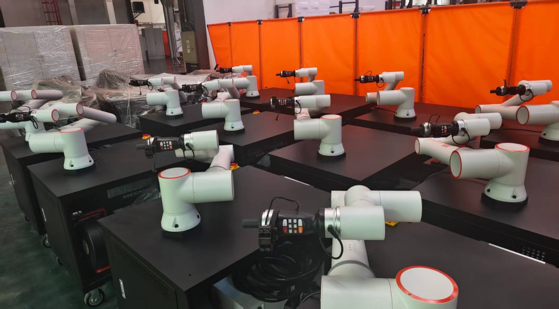
3.1 Heat Input Management
The Intelligent Arc Control system was programmed with a pulse-on-pulse waveform specifically tuned for thin-gauge stainless. By using the Collaborative Arc Welding System, we could maintain a consistent travel speed of 18-22 inches per minute (IPM), which is difficult for manual welders to sustain over an eight-hour shift without fatigue-induced weaving. This consistency is the cornerstone of Automated Welding. By keeping the heat input between 0.5 and 1.2 kJ/mm, we effectively eliminated the “warping” that previously required post-weld straightening—a hidden cost that plagued the Indiana plant’s margins for years.
3.2 Shielding Gas Dynamics and Oxidation
Stainless steel is unforgiving regarding atmospheric contamination. We implemented a secondary trailing shield integrated into the cobot’s torch mount. The Automated Welding software was configured to include a pre-flow of 2.0 seconds and a post-flow of 5.0 seconds. In a collaborative environment, the “intelligent” aspect monitored the gas flow rate. If the flow dropped below 25 CFH (Cubic Feet per Hour) due to a kinked line or a depleted tank, the system triggered an emergency stop, preventing the oxidation of expensive stainless workpieces. This “fail-safe” is a critical component of Stainless Steel welding where rework is often more expensive than the original part.
4.0 Intelligent Arc Control Implementation and Waveform Analysis
The core of the “Intelligent” label lies in the feedback loop. During the Indiana field tests, we utilized high-speed data logging to monitor the arc’s “heartbeat.”
4.1 Gap Bridging and Adaptive Fill
In manual Stainless Steel welding, a welder compensates for poor fit-up by slowing down or oscillating the torch. Our Collaborative Arc Welding System utilized an “Arc Sense” software module. As the cobot moved along the seam, the system measured the current. A dip in current suggested a wider gap; the Automated Welding logic responded by increasing the weave amplitude and decreasing travel speed. This adaptive fill capability reduced our scrap rate on the 304L tanks from 8% to less than 0.5%.
4.2 Spatter Reduction through Surface Tension Transfer
Spatter on stainless steel is not just an aesthetic issue; it’s a corrosion site. We utilized a modified short-circuit transfer mode provided by the Intelligent Arc Control. By precisely timing the current reduction at the moment of droplet detachment, we virtually eliminated spatter. This saved the Indiana facility approximately 14 man-hours per week in post-weld grinding and pickling paste application.
5.0 Field Data and Results
The transition to an Automated Welding workflow yielded quantifiable improvements. Over 500 units of SS 304 pressure vessels, the following metrics were recorded:
- Duty Cycle Increase: From 25% (manual) to 78% (collaborative).
- Consumable Efficiency: 15% reduction in wire waste due to optimized “crater fill” routines at the end of each weld.
- Heat Affected Zone (HAZ): Metallurgical cross-sections showed a 30% reduction in HAZ width compared to manual TIG, improving the long-term fatigue life of the joints.
6.0 Lessons Learned: The “Indiana” Friction Points
No field report is complete without addressing the “technical friction” encountered on the shop floor. Engineering is rarely as clean as the CAD model suggests.
6.1 Grounding and Electrical Noise
The Indiana facility was an older structure with inconsistent electrical grounding. We found that the sensitive sensors in the Collaborative Arc Welding System were picking up electromagnetic interference (EMI) from a neighboring 50-year-old overhead crane. This caused “ghost” collisions where the cobot would stop, thinking it had hit an object. Lesson learned: Always perform a dedicated grounding audit and install high-frequency noise filters before deploying intelligent arc systems in older industrial environments.
6.2 The “Black Box” Syndrome
Initially, the veteran welders were skeptical of Automated Welding. They viewed the Intelligent Arc Control as a “black box” that didn’t understand the “feel” of the metal. We resolved this by involving the senior welders in the parameter-tuning phase. Once they saw they could “teach” the cobot their specific weave patterns and that the Collaborative Arc Welding System would replicate it perfectly every time, the culture shifted from resistance to ownership.
6.3 Stainless Steel Surface Preparation
We discovered that the Automated Welding system was highly sensitive to surface contaminants—specifically the oils used in the upstream rolling process. While a manual welder might “burn through” a bit of oil, the intelligent sensors detected the arc instability and fluctuated the voltage, leading to porosity. Lesson learned: Automation demands higher upstream discipline. We had to implement a mandatory acetone wipe-down protocol for all Stainless Steel welding prep to ensure the sensors weren’t chasing phantoms.
7.0 Conclusion
The integration of an Intelligent Arc Control Collaborative Arc Welding System in the Indiana field test proved that Automated Welding is no longer reserved for high-volume automotive assembly lines. For Stainless Steel welding, the benefits of precision heat control and repeatable metallurgical outcomes outweigh the initial capital expenditure.
The synergy between the cobot’s physical flexibility and the intelligent system’s electrical adaptability allows mid-sized American manufacturers to compete globally. However, success depends on more than just the hardware; it requires a rigorous focus on grounding, surface prep, and the integration of veteran welding expertise into the digital weld schedule. As we move forward, the focus will shift toward AI-driven predictive maintenance for these systems, ensuring the arc never stays extinguished for long.
Report Prepared By: Senior Welding Engineer, Field Operations Division
Location: Indiana, USA
Subject: Automated SS Systems Rollout
-


Cantilever Welding Robot solution
-


GF laser cutting machine
-

P3015 plasma cutting machine
-

LFP3015 Fiber Laser Cutter
-

pipe plasma cutting machine
-
LFH 4020 Fiber Laser Cutting Machine
-
LFP4020
-

gantry plasma air cutting machine
-

3D robot cutting machine
-

8 axis plasma cutting machine
-

5 axis plasma cutting machine
-

LT360 tube laser cutting machine
-

robot welding workstation
-

SF6060 fiber laser cutting machine
Advanced Fiber Laser Tube Processing Technology
Our CNC Fiber Laser Tube Cutting systems revolutionize metal fabrication by integrating high-precision cutting, punching, and profiling into a single automated workflow. Designed for versatility, this technology handles a wide array of profiles including Round, Square, Rectangular, and Oval tubes, as well as complex L-shaped and U-shaped channels.
- Precision Punching: High-speed hole punching with micron-level accuracy, eliminating the need for mechanical drilling or die-stamping.
- Complex Profiling: Advanced 3D pathing allows for intricate interlocking joints and specialized notch cuts, ideal for structural frames.
- High Material Efficiency: Intelligent nesting software minimizes scrap, reducing raw material costs across large production runs.
- Clean Finish: Delivers oxide-free, burr-free edges that require zero secondary grinding before welding.

Seamlessly processing multiple profiles with consistent precision.
Global Delivery & Logistics



From our high-tech manufacturing facility directly to your global site. PCL WeldCut ensures secure packaging, professional handling, and reliable international logistics to safeguard your equipment throughout the entire journey.