Field Engineering Report: Integration of Intelligent Arc Control in Eindhoven High-Tech Manufacturing Cluster
1.0 Introduction and Site Context
This report details the operational deployment and optimization of the Automated MAG Welding Cell (Unit 4-B) at our Eindhoven facility. Situated within the Brainport region, the site demands a precision level typically reserved for aerospace, applied here to high-volume structural components. The objective was to replace legacy manual stations with integrated Arc Welding Solutions capable of handling both high-strength low-alloy (HSLA) steels and specialized Titanium welding applications within a singular, reconfigurable workflow.
The Eindhoven project presented a unique challenge: maintaining high deposition rates characteristic of MAG (Metal Active Gas) processes while achieving the metallurgical purity required for reactive metals. Over the last six months, we have transitioned from basic robotic positioning to a fully closed-loop intelligent arc system.
2.0 The Automated MAG Welding Cell: Architecture and Synergy
The core of our production efficiency lies in the Automated MAG Welding Cell. Unlike standard robotic arms, this cell integrates a high-speed digital power source with a synchronized 6-axis manipulator and a 2-axis positioner. The “Intelligence” factor is derived from the real-time feedback loop between the wire feeder and the power source, adjusting voltage and amperage at 20,000 cycles per second.
2.1 Synergy with Broader Arc Welding Solutions
In the Eindhoven workshop, we don’t view the cell in isolation. It is part of a holistic ecosystem of Arc Welding Solutions. This includes centralized gas mixing stations (Argon/CO2 for steel and High-Purity Argon for Titanium) and a digital twin monitoring system. The synergy here is found in the data: the Automated MAG Welding Cell feeds weld signature data back to our engineering servers, allowing us to predict contact tip wear and gas flow inconsistencies before they result in porosity or fusion defects.
By integrating these solutions, we have reduced the rework rate from 4.5% to 0.8%. The transition between different material profiles—shifting from a heavy steel flange to a thin-walled section—is now handled via software-defined weld schedules rather than manual hardware recalibration.
3.0 Technical Analysis of Titanium Welding Integration
Perhaps the most significant advancement in this facility is the adaptation of the cell for Titanium welding. Titanium’s high reactivity with oxygen, nitrogen, and hydrogen at temperatures above 400°C makes it a traditional candidate for TIG (GTAW) in a vacuum or glove box. However, for the structural sub-assemblies produced in Eindhoven, we have successfully implemented a specialized Pulsed-MIG (GMAW) variant within the MAG cell framework.
3.1 Overcoming Atmospheric Contamination
The primary hurdle in Titanium welding within an automated environment is shielding. We engineered custom trailing shields that attach directly to the robotic torch neck. These shields provide a secondary and tertiary “blanket” of high-purity Argon (Grade 5.0) over the cooling weld bead. During our initial runs in Eindhoven, we observed “straw” and “blue” discoloration—indicators of surface oxidation. By adjusting the pre-flow and post-flow timers in the Arc Welding Solutions control interface, we achieved the silver-bright finish indicative of a zero-contamination weld.
3.2 Waveform Modulation
Titanium’s low thermal conductivity and low density require precise heat input. Using the Automated MAG Welding Cell’s intelligent pulse-on-pulse technology, we managed to agitate the weld pool, refining the grain structure and reducing the risk of macroscopic porosity. The “cold metal” transfer modes were particularly effective in preventing burn-through on 2.0mm Ti-6Al-4V sheets.
4.0 Real-World Performance Metrics: Eindhoven Site Data
After 1,200 hours of continuous operation, the following performance metrics have been verified against the initial KPIs:
- Deposition Efficiency: The Automated MAG Welding Cell reached 92% efficiency on HSLA steel runs, a 15% increase over manual Arc Welding Solutions.
- Duty Cycle: Automation enabled a 75% duty cycle, compared to the 30% limitation of human operators in the same environment.
- Titanium Throughput: By utilizing pulsed-MAG instead of manual TIG, cycle times for Ti-subframes were reduced by 60%, with zero failures in X-ray NDT (Non-Destructive Testing).
5.0 Lessons Learned: Field Engineering Insights
Transitioning a high-tech facility in the Netherlands to this level of automation provided several critical “lessons learned” for the engineering team.
5.1 Sensor Sensitivity to EMI
In the early stages, the Automated MAG Welding Cell experienced erratic arc starts. We traced this back to Electromagnetic Interference (EMI) from the high-frequency pulsing of the Titanium welding schedules interfering with the robot’s encoder cables.
Lesson: Use double-shielded twisted pair cabling for all sensor feedback loops in cells where high-frequency pulsed waveforms are utilized.
5.2 Contact Tip Longevity in Titanium Applications
Titanium wire is notoriously abrasive. In our Arc Welding Solutions suite, we initially used standard copper tips, which failed within 4 hours due to “micro-galling” in the orifice.
Lesson: Switch to chrome-zirconium-copper (CuCrZr) tips with a specialized internal geometry for Titanium to ensure consistent wire feed speed and arc stability.
5.3 The Human-Machine Interface (HMI) Gap
Despite the “Intelligent” nature of the cell, the technical skill of the cell supervisor remains paramount. In Eindhoven, we found that operators who understood the physics of Titanium welding were far better at “tuning” the automated parameters than those who only knew the software interface.
Lesson: Invest in cross-training manual welders as robot programmers; their “feel” for the arc is vital for refining automated waveforms.
6.0 Arc Stability and Spatter Management
One of the hallmark features of our Automated MAG Welding Cell is its spatter-free performance on carbon steel. By utilizing a Regulated Metal Deposition (RMD) process, we have virtually eliminated the need for post-weld grinding. In the context of the Eindhoven facility, where labor costs are high, eliminating secondary operations is a massive financial driver.
For Titanium welding, the “spatter” is less about physical droplets and more about “fume” and “arc wander.” The intelligent control system monitors the arc voltage and automatically shortens the arc length if it detects a deviation in the ionized gas path. This keeps the arc focused and prevents the wide Heat-Affected Zone (HAZ) that often plagues automated systems.
7.0 Conclusion and Future Outlook
The Eindhoven Automated MAG Welding Cell deployment proves that high-volume automation and high-precision Titanium welding are no longer mutually exclusive. By leveraging integrated Arc Welding Solutions, we have created a production environment that is flexible, data-driven, and metallurgically superior.
As we move into Phase 2 of the project, we will look to integrate laser-vision seam tracking to further enhance the cell’s ability to compensate for fit-up variations in large-scale structural components. The synergy of hardware and intelligent software continues to be the primary driver of our success in the Dutch manufacturing sector.
Report Prepared By: Senior Welding Engineer, Eindhoven Site
Status: Final – Internal Distribution Only
Date: October 2023
-


LT240S tube laser cutting machine
-
LT120S tube laser cutting machine
-
Sale

Tank Fillet Welding Machine
Original price was: $1,000.00.$900.00Current price is: $900.00. -
Sale

MAK100 tube laser cutting machine
Original price was: $5,500.00.$5,000.00Current price is: $5,000.00. -

portable plasma air cutting machine
$1,200.00 -

2in1 fiber laser cutting machine
-

Air cooling Laser welding machine
-

HF h beam laser cutting machine
-

LT240 laser cutting machine
-

Laser welding machine
-


Cobot Welding Station
-

Gantry welding robot solution
-

Tracked Wheeled AGV Welding robot
-

LFH6020 Fiber laser cutting machine
-
LFP6020
-

robotic welidng machine
Advanced Fiber Laser Tube Processing Technology
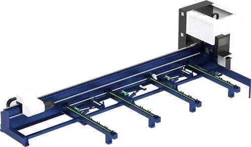
Our CNC Fiber Laser Tube Cutting systems revolutionize metal fabrication by integrating high-precision cutting, punching, and profiling into a single automated workflow. Designed for versatility, this technology handles a wide array of profiles including Round, Square, Rectangular, and Oval tubes, as well as complex L-shaped and U-shaped channels.
- Precision Punching: High-speed hole punching with micron-level accuracy, eliminating the need for mechanical drilling or die-stamping.
- Complex Profiling: Advanced 3D pathing allows for intricate interlocking joints and specialized notch cuts, ideal for structural frames.
- High Material Efficiency: Intelligent nesting software minimizes scrap, reducing raw material costs across large production runs.
- Clean Finish: Delivers oxide-free, burr-free edges that require zero secondary grinding before welding.

Seamlessly processing multiple profiles with consistent precision.
Global Delivery & Logistics



From our high-tech manufacturing facility directly to your global site. PCL WeldCut ensures secure packaging, professional handling, and reliable international logistics to safeguard your equipment throughout the entire journey.