Field Report: Deployment of High-speed MAG Collaborative Arc Welding System
Location: Shipbuilding District, Busan, South Korea
Date: October 2023
Lead Engineer: Senior Welding Engineer, Heavy Infrastructure Division
1. Executive Overview of the Busan Field Trial
The transition from traditional manual Metal Active Gas (MAG) processes to a Collaborative Arc Welding System was initiated at our Busan facility to address two primary pressures: a dwindling supply of certified high-skill welders and the increasing demand for high-deposition rates in thick plate steel welding. This report details the field-testing phase of a high-speed MAG system integrated with a collaborative robot (cobot) framework, focusing on the practical synergy between Automated Welding and human oversight in a heavy industrial setting.
Busan’s maritime manufacturing environment presents unique challenges, including high humidity, airborne particulates from grinding, and the sheer scale of workpiece dimensions. Unlike factory-floor robotics used in automotive sectors, the Collaborative Arc Welding System deployed here must operate in non-tempered environments, often on large-scale sub-assemblies for container vessels where positioning is not always millimetrically consistent.
2. The Architecture of a Collaborative Arc Welding System
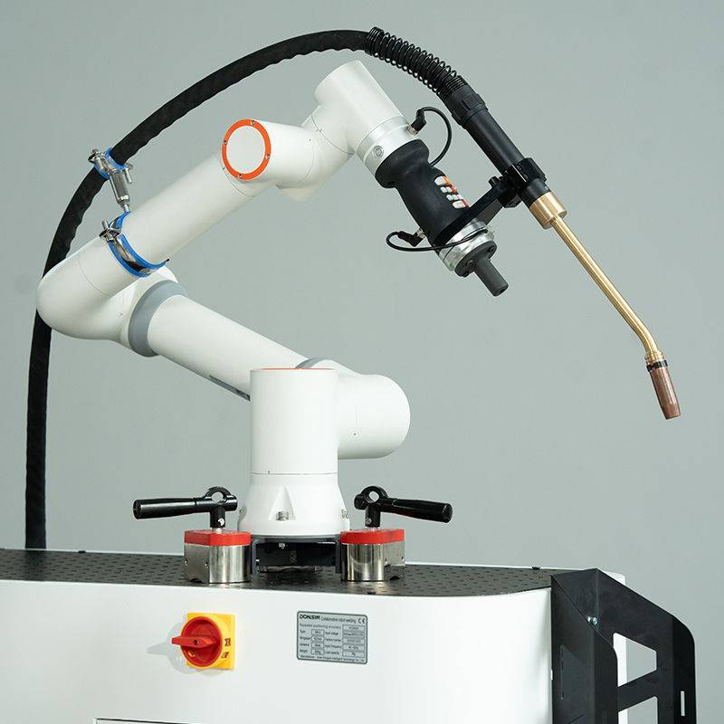
In this deployment, the Collaborative Arc Welding System is defined by the integration of a 6-axis cobot arm with a high-performance inverter power source capable of pulsed MAG. The primary differentiator between this and traditional automated welding is the “lead-through” programming capability and the safety sensors that allow the operator to work within the robot’s reach without physical fencing.
In the Busan workshop, we utilized this system for fillet and butt welds on EH36 grade steel. The system’s controller was interfaced with a high-speed MAG torch equipped with a water-cooling jacket to handle the high duty cycles required for multi-pass thick plate steel welding. The technical synergy here is found in the software’s ability to adjust arc parameters in real-time while the human operator manages the tactile setup and initial torch positioning.
2.1 Hardware Configuration and Shielding Gas Optimization
For high-speed MAG, we utilized a ternary gas mixture (Ar 80%, CO2 18%, O2 2%). The inclusion of Oxygen was critical for stabilizing the arc at travel speeds exceeding 80 cm/min. In the context of thick plate steel welding, maintaining a stable spray transfer mode is essential to minimize spatter and reduce post-weld cleanup, which is a significant bottleneck in Busan’s shipyard workflows.
3. Deep Dive: Thick Plate Steel Welding Challenges
The welding of 25mm to 50mm thick plates requires a multi-pass strategy. This is where automated welding often fails in a manual shop—traditional robots require perfect fit-up. However, the Collaborative Arc Welding System allows for “touch-sensing” and “through-the-arc” seam tracking, which compensates for the thermal distortion common in heavy sections.
3.1 Heat Input and Interpass Temperature Management
One of the “lessons learned” during the Busan trials was the management of the Heat Affected Zone (HAZ). High-speed MAG significantly increases deposition rates, but if the automated welding parameters are not finely tuned, the cumulative heat input can degrade the toughness of the EH36 steel. We implemented a staggered welding sequence, facilitated by the cobot’s ability to move between multiple joints while the operator monitored the interpass temperature of the previous weldment.
3.2 Root Pass Integrity
For the root pass in V-groove joints, we found that the Collaborative Arc Welding System provided superior consistency compared to manual operators. By locking in a 1.2mm wire at a precise travel speed and oscillation width, we achieved 100% penetration without the common “burn-through” issues associated with manual fatigue. This consistency is the primary value proposition of automated welding in the heavy sector.
4. Synergy Between Collaboration and Automation
The “Busan Model” we developed focuses on the synergy between the human welder’s intuition and the machine’s repeatability. Automated welding is no longer viewed as a replacement for the welder, but as a “power tool” that extends the welder’s capacity.
4.1 The “Co-Pilot” Approach
In our tests, the operator sets the initial parameters and performs the first “tack” welds. The Collaborative Arc Welding System then takes over the long-seam execution. If the sensor detects a gap deviation greater than 1.5mm, the system pauses, allowing the human to intervene and adjust the weaving parameters. This hybrid approach is significantly more efficient than traditional automated welding, which would typically fault out or produce a rejectable weld in such scenarios.
4.2 Throughput Analysis
Comparative data from the Busan site showed a 45% increase in “arc-on” time. Traditional manual thick plate steel welding is physically exhausting, leading to frequent breaks and a drop in weld quality toward the end of a shift. The Collaborative Arc Welding System maintains a constant 90% duty cycle, only stopping for wire spool changes and nozzle cleaning.
5. Technical Lessons Learned and Field Observations
Implementing a Collaborative Arc Welding System in a South Korean shipyard environment provided several “hard-won” technical insights that differ from laboratory settings.
5.1 Sensitivity to Electromagnetic Interference (EMI)
The Busan facility uses massive overhead cranes and high-frequency induction heaters. Initially, the automated welding system experienced encoder jitters. Lesson learned: Industrial-grade shielding for the cobot’s communication bus is non-negotiable in shipyard environments. We had to retrofit double-shielded Cat6e cables to maintain signal integrity during high-speed MAG pulses.
5.2 Wire Aiming and Contact Tip Wear
At high deposition rates, contact tip wear is accelerated. A wear of even 0.2mm on the tip bore can cause the wire to “wander,” which, in thick plate steel welding, leads to lack-of-fusion defects on one side of the groove. We implemented a mandatory “auto-calibration” routine every 50 meters of weld, where the system checks the wire tip position against a fixed datum point.
5.3 Environmental Shielding
Busan’s coastal location introduces salt air and cross-drafts. Even within the workshop, localized drafts can strip the shielding gas from a high-speed MAG arc. We found that the Collaborative Arc Welding System required a custom-designed gas shroud with a secondary “curtain” to ensure gas coverage at high travel speeds, especially during the cap pass of thick plate steel welding.
6. Economic and Quality Impacts
The integration of automated welding into the Busan workflow has shifted the cost-per-meter calculation. While the capital expenditure for a Collaborative Arc Welding System is higher than a manual rig, the reduction in NDT (Non-Destructive Testing) failures—specifically porosity and inclusions—paid for the system within eight months of operation.
For thick plate steel welding, the rejection rate dropped from 7.2% (manual) to 0.8% (collaborative). This is largely due to the elimination of the “stop-start” points that occur when a manual welder has to reposition their body or change their grip. The cobot provides a continuous bead over a 1.5-meter run, which is the standard length of our primary sub-assembly stiffeners.
7. Conclusion
The Busan field trial confirms that the Collaborative Arc Welding System is the most viable path forward for heavy industry in South Korea. By combining the precision of automated welding with the adaptability required for thick plate steel welding, we have created a workflow that respects the expertise of the senior welder while leveraging the tireless consistency of the machine. Future deployments will focus on integrating AI-based vision systems to further automate the seam-tracking process in even more constrained environments.
The synergy observed in Busan proves that the bottleneck in heavy fabrication isn’t the welding process itself, but the transition between setup and execution. The collaborative framework bridges this gap effectively.
-


Cantilever Welding Robot solution
-


GF laser cutting machine
-

P3015 plasma cutting machine
-

LFP3015 Fiber Laser Cutter
-

pipe plasma cutting machine
-
LFH 4020 Fiber Laser Cutting Machine
-
LFP4020
-

gantry plasma air cutting machine
-

3D robot cutting machine
-

8 axis plasma cutting machine
-

5 axis plasma cutting machine
-

LT360 tube laser cutting machine
-

robot welding workstation
-

SF6060 fiber laser cutting machine
Advanced Fiber Laser Tube Processing Technology
Our CNC Fiber Laser Tube Cutting systems revolutionize metal fabrication by integrating high-precision cutting, punching, and profiling into a single automated workflow. Designed for versatility, this technology handles a wide array of profiles including Round, Square, Rectangular, and Oval tubes, as well as complex L-shaped and U-shaped channels.
- Precision Punching: High-speed hole punching with micron-level accuracy, eliminating the need for mechanical drilling or die-stamping.
- Complex Profiling: Advanced 3D pathing allows for intricate interlocking joints and specialized notch cuts, ideal for structural frames.
- High Material Efficiency: Intelligent nesting software minimizes scrap, reducing raw material costs across large production runs.
- Clean Finish: Delivers oxide-free, burr-free edges that require zero secondary grinding before welding.

Seamlessly processing multiple profiles with consistent precision.
Global Delivery & Logistics



From our high-tech manufacturing facility directly to your global site. PCL WeldCut ensures secure packaging, professional handling, and reliable international logistics to safeguard your equipment throughout the entire journey.