Field Engineering Report: Implementation of High-Speed MAG Collaborative Arc Welding
Date: October 14, 2024
Location: Fabrication Facility, Rocklea, Brisbane, QLD
Project Reference: BR-MAG-09-ThinSheet
Executive Summary of Site Operations
This report details the field deployment and performance calibration of a high-speed MAG (Metal Active Gas) Collaborative Arc Welding System within a medium-scale manufacturing environment in Brisbane. The objective was to transition a manual production line for HVAC ducting and light-gauge structural components into a semi-autonomous workflow. By integrating Automated Welding protocols with human-collaborative interfaces, we addressed the specific challenges of thin metal sheet welding—primarily thermal distortion and burn-through—while navigating the high-humidity environmental factors typical of South East Queensland.
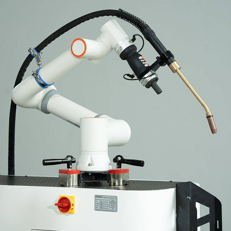
1. The Mechanics of the Collaborative Arc Welding System
The core of the installation is a 6-axis collaborative robot (cobot) integrated with a high-performance pulsed-MAG power source. Unlike traditional industrial robots that require extensive safety cells and specialized PLC programming, the Collaborative Arc Welding System used here allows Brisbane-based fabricators to work alongside the arm. The “collaborative” aspect is not merely a safety rating; it is a functional shift in how we approach Automated Welding.
1.1. Hand-Guiding and Lead-Through Programming
In our Rocklea trials, we utilized lead-through programming to define complex weld paths on 1.6mm mild steel assemblies. The lead engineer or senior welder physically moves the torch through the required trajectory, recording “waypoints.” This bypasses the need for a dedicated robotics engineer on-site. For thin metal sheet welding, where joint fit-up varies by fractions of a millimeter, the ability for a floor welder to “tweak” a program in under two minutes is the difference between a viable automated solution and a bottleneck.
1.2. Safety and Shop Floor Integration
The system operates under ISO 15066 standards. In the Brisbane facility, space is at a premium. By utilizing a Collaborative Arc Welding System, we eliminated the need for heavy fencing, allowing the automated welding unit to be moved via pallet jack between different workstations. This mobility is crucial for local workshops that handle diverse, small-batch contracts rather than long-run automotive-style production.
2. Synergy: Transitioning to Automated Welding
The synergy between the collaborative hardware and the automated welding logic lies in the repeatability of the “arc-on” time. Manual welding of thin metal sheets is prone to “stop-start” defects and inconsistent travel speeds, which leads to excessive heat input.
2.1. Travel Speed Consistency
Automated welding allows us to maintain a constant travel speed of 800mm/min to 1200mm/min—speeds that are difficult for a manual welder to sustain with precision on a 1.2mm radius. By automating the motion, we stabilize the weld pool. In the Brisbane heat, operator fatigue usually leads to a 15% drop-off in weld quality toward the end of a shift; the cobot eliminates this variable, ensuring the first weld at 7:00 AM is identical to the last at 3:30 PM.
2.2. Parameter Syncing
The Collaborative Arc Welding System communicates directly with the power source via a high-speed digital bus. This allows for “on-the-fly” adjustments. As the automated welding sequence progresses, the system can adjust wire feed speed (WFS) and voltage based on the torch’s position, which is essential when transitioning from a flat position to a vertical-down position on a single thin-sheet component.
3. Technical Challenges in Thin Metal Sheet Welding
Thin metal sheet welding (specifically 0.8mm to 2.0mm) is the “acid test” for any automated system. The margin for error regarding heat input is razor-thin. If the arc lingers for even 100 milliseconds too long, the result is a blow-through that requires manual rework, defeating the purpose of automation.
3.1. Managing Thermal Distortion
In our Brisbane trials, we were working with 1.5mm galvanized steel. Thermal distortion is the primary enemy here. We implemented a “pulsed-MAG” strategy within the automated welding sequence. By pulsing the current, we achieved deep penetration at the peak of the pulse while allowing the weld pool to cool during the background current phase. This lowered the overall Heat Affected Zone (HAZ), keeping the thin metal sheets flat and reducing the need for post-weld straightening.
3.2. Gap Bridging and Fit-up
Automated welding typically requires near-perfect fit-up. However, in real-world Brisbane workshops, sheet metal tolerances can be loose. We programmed the Collaborative Arc Welding System to perform a slight “weave” pattern (1.5mm amplitude). This weave allows the arc to bridge gaps that would otherwise cause a linear automated weld to fail. This flexibility makes the system “collaborative” in a broader sense—it compensates for the realities of manual upstream processes (like manual shearing or bending).
4. Lessons Learned: The Brisbane Field Experience
Working in the Brisbane industrial sector provides unique variables that aren’t always covered in European or North American technical manuals. Humidity and local power grid fluctuations played a significant role in our calibration phase.
Lesson 1: Shielding Gas Stability and Humidity
Brisbane’s high humidity can lead to moisture contamination in the shielding gas lines, causing porosity in MAG welding. We found that the high-speed nature of automated welding exacerbates this. We had to install point-of-use gas dryers and increase the flow rate of the Ar/CO2 (80/20) mix slightly to 18L/min to ensure the arc remained stable during high-speed travel. For thin metal sheet welding, even minor porosity can lead to a structural failure of the joint.
Lesson 2: Wire Feed Reliability
We initially experienced “bird-nesting” at the drive rolls. With high-speed MAG, the wire is fed at rates exceeding 10m/min. We learned that for thin metal sheet welding, using a 0.8mm wire is preferable over 1.0mm, as it allows for a higher current density at lower total heat inputs. However, 0.8mm wire is prone to buckling. The lesson: Use a dual-drive four-roller feeder even on a cobot setup to ensure the automated welding process doesn’t stutter.
Lesson 3: Grounding and Electrical Noise
The Collaborative Arc Welding System is sensitive to EMF. In an older Rocklea workshop with legacy TIG machines nearby, we encountered communication lag between the cobot and the welder. Proper “Star Point” grounding was required to ensure the automated welding signals weren’t interrupted. If the signal drops for a millisecond, the cobot might stop, but the arc might stay on—a recipe for a hole in your thin metal sheet.
5. Synergy and Productivity Gains
The integration of these technologies resulted in a 40% increase in throughput for the ducting assembly line. But the true value was found in the synergy between the human operator and the machine. The welder became a “cell manager.” While the Collaborative Arc Welding System handled the long, repetitive seams on the thin metal sheets, the welder performed the complex tacks and quality inspections.
5.1. Reduced Rework
Before the implementation of the automated welding system, rework rates due to distortion on 1.2mm sheets were at 12%. Post-implementation, this dropped to less than 2%. The precision of the Collaborative Arc Welding System in controlling the “crater fill” at the end of a weld run solved the common issue of end-point cracking in thin-gauge materials.
5.2. Skill Augmentation
A significant “lesson learned” was the impact on the local workforce. Younger welders in the Brisbane area picked up the tablet-based interface of the Collaborative Arc Welding System within hours. It bridges the gap between traditional trade skills and the modern requirement for high-tech manufacturing, making thin metal sheet welding less of a “black art” and more of a repeatable science.
6. Final Recommendations
For firms in Brisbane looking to adopt a Collaborative Arc Welding System for thin metal sheet welding, I recommend the following:
- Invest in Tooling: Automated welding is only as good as the jigging. Ensure your clamps are robust and don’t interfere with the cobot’s reach.
- Monitor Consumables: High-speed MAG wears contact tips faster. Use chrome-zirconium tips to maintain conductivity over long shifts.
- Optimize Pulse Settings: Don’t rely on factory presets. Calibrate your pulse frequency specifically for the material thickness and local gas quality.
The transition to a Collaborative Arc Welding System in the Rocklea facility has proven that automated welding is no longer reserved for the automotive giants. For the Brisbane fabricator, it is a practical, scalable solution to the challenges of thin metal sheet welding.
End of Report.
Signed,
Senior Welding Engineer
AS/NZS 1554.1 Certified Specialist
-


Cantilever Welding Robot solution
-


GF laser cutting machine
-

P3015 plasma cutting machine
-

LFP3015 Fiber Laser Cutter
-

pipe plasma cutting machine
-
LFH 4020 Fiber Laser Cutting Machine
-
LFP4020
-

gantry plasma air cutting machine
-

3D robot cutting machine
-

8 axis plasma cutting machine
-

5 axis plasma cutting machine
-

LT360 tube laser cutting machine
-

robot welding workstation
-

SF6060 fiber laser cutting machine
Advanced Fiber Laser Tube Processing Technology
Our CNC Fiber Laser Tube Cutting systems revolutionize metal fabrication by integrating high-precision cutting, punching, and profiling into a single automated workflow. Designed for versatility, this technology handles a wide array of profiles including Round, Square, Rectangular, and Oval tubes, as well as complex L-shaped and U-shaped channels.
- Precision Punching: High-speed hole punching with micron-level accuracy, eliminating the need for mechanical drilling or die-stamping.
- Complex Profiling: Advanced 3D pathing allows for intricate interlocking joints and specialized notch cuts, ideal for structural frames.
- High Material Efficiency: Intelligent nesting software minimizes scrap, reducing raw material costs across large production runs.
- Clean Finish: Delivers oxide-free, burr-free edges that require zero secondary grinding before welding.

Seamlessly processing multiple profiles with consistent precision.
Global Delivery & Logistics


From our high-tech manufacturing facility directly to your global site. PCL WeldCut ensures secure packaging, professional handling, and reliable international logistics to safeguard your equipment throughout the entire journey.