Engineering Review: High-speed MAG Cobot Welding Machine – Ohio, USA
In this article
- Field Report: High-Speed MAG Deployment in Northeast Ohio Automotive Tier-2 Facility
- 1. Introduction and Site Context
- 2. The Hardware Interface: Defining the Cobot Welding Machine
- 3. Practical Application of Collaborative Robotics
- 4. Technical Nuances of Stainless Steel Welding with MAG
- 5. Synergy Between Robot and Power Source
- 6. Field Lessons Learned
- 7. Production Metrics and ROI
- 8. Conclusion
Field Report: High-Speed MAG Deployment in Northeast Ohio Automotive Tier-2 Facility
1. Introduction and Site Context
This report summarizes the three-week deployment and optimization phase of a high-speed MAG (Metal Active Gas) Cobot Welding Machine at a fabrication facility in Northeast Ohio. The facility specializes in exhaust components and fluid handling systems, primarily utilizing 304L and 316L grades.
The primary objective was to transition high-volume Stainless Steel welding tasks from manual stations to a system utilizing Collaborative Robotics. The Ohio labor market remains tight for certified 6G welders; therefore, the strategy focused on “upskilling” existing operators to manage robotic cells. This deployment specifically addressed the challenges of high-speed travel rates (exceeding 30 inches per minute) while maintaining structural integrity and aesthetic requirements.
2. The Hardware Interface: Defining the Cobot Welding Machine
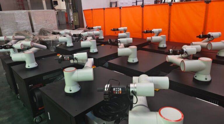
The unit deployed is a 6-axis collaborative arm integrated with a high-performance inverter power source. Unlike traditional industrial robots, this Cobot Welding Machine lacks the massive footprint of safety fencing, instead relying on localized laser scanners and power/force limiting (PFL) sensors.
2.1. Power Source Integration
For this Ohio-based production line, we utilized a pulsed-MAG waveform. Standard CV (Constant Voltage) was insufficient for the 1.5mm thin-wall stainless tubing. The power source was digitally coupled to the cobot controller, allowing for real-time adjustment of trim and wire feed speed (WFS) mid-path. This synergy is critical when the cobot approaches tight radii where travel speed naturally fluctuates.
2.2. Torch and Consumables
We utilized a liquid-cooled torch specifically designed for high duty cycles. A common mistake in these setups is using air-cooled torches to save on cost; however, at the travel speeds required for this project, the heat soak into the contact tip led to micro-arcing and wire burn-back. Switching to a liquid-cooled system stabilized the TCP (Tool Center Point) throughout the 10-hour shift.
3. Practical Application of Collaborative Robotics
The term Collaborative Robotics often gets dismissed as a buzzword, but on the Ohio shop floor, its utility was proven through “Lead-Through Programming.”
3.1. Rapid Prototyping and Path Teaching
The senior welder on-site, who had zero previous coding experience, was able to grab the robot flange and “teach” the path for a complex manifold joint in under ten minutes. By physically moving the Cobot Welding Machine through the weldment, the operator accounted for fit-up variations that a remote programmer might miss. This “human-in-the-loop” approach reduced the commissioning time by 40% compared to traditional caged systems.
3.2. Safety and Spatial Efficiency
Due to the floor plan constraints typical of older Ohio industrial buildings, the ability to place the cobot directly next to manual prep stations was vital. We configured the “Safety Zones” so the robot slows to 10% speed if an operator enters the secondary perimeter and executes an emergency stop (E-Stop) only upon contact or breach of the primary zone.
4. Technical Nuances of Stainless Steel Welding with MAG
Stainless Steel welding using the MAG process requires a precise gas mixture to avoid carbon pickup and maintain corrosion resistance. In this application, we utilized a 98% Argon / 2% CO2 mix.
4.1. Managing Heat Input
The biggest hurdle was the warping of 304L stainless. At high speeds, the cobot can outrun the shielding gas envelope if the nozzle design is inadequate. We implemented a “Stitch Weld” logic within the cobot’s software to manage the heat-affected zone (HAZ).
4.2. Wire Selection and Feedability
We transitioned from standard ER308L to an ER308LSi wire. The higher silicon content improved the wetting of the puddle edges—a necessity when the Cobot Welding Machine is moving at 35 IPM. Without the improved fluidity provided by the “Si” variant, we observed “humping” of the bead and lack of sidewall fusion at the start-stop points.
5. Synergy Between Robot and Power Source
The integration of Collaborative Robotics with advanced pulse-welding software allowed us to implement “Adaptive Fill.” In Northeast Ohio, humidity shifts significantly between seasons, often affecting the surface tension of the weld pool. By using a Cobot Welding Machine equipped with a “Seam Tracking” sensor, the system could detect slight gaps in the stainless fit-up and automatically adjust the weave width and WFS to compensate, preventing burn-through.
6. Field Lessons Learned
6.1. The “Tack Weld” Conflict
A major lesson learned was the impact of manual tack welds. Manual tacks are often oversized and inconsistent. When the Cobot Welding Machine encountered a heavy tack, the arc voltage would spike, causing the robot to “stutter” as it attempted to maintain the arc length.
*Lesson:* We had to standardize tacking procedures using a dedicated jig, ensuring tacks were no larger than 2mm to allow the cobot to “wash over” them without disrupting the travel speed.
6.2. Grounding and Interference
We encountered intermittent communication drops between the cobot and the welder. The culprit was high-frequency (HF) interference. Even though MAG doesn’t use HF start like TIG, the inverter’s high-speed switching was creating “noise.”
*Lesson:* Ensure the cobot controller and the welding power source share a common, dedicated ground. Do not rely on the building’s structural steel in older facilities.
6.3. Gas Flow Dynamics at High Speed
When the Collaborative Robotics system moves at high velocity, it creates a venturi effect, pulling atmospheric oxygen into the shielding gas stream.
*Lesson:* We increased the gas flow from 30 CFH to 45 CFH and utilized a large-diameter gas lens. This ensured the Stainless Steel welding remained “straw-colored” rather than turning grey/black (indicating heavy oxidation).
7. Production Metrics and ROI
Prior to the installation of the Cobot Welding Machine, the manual output was 12 units per hour with a 15% reject rate due to aesthetic inconsistencies.
Post-deployment results:
– Output: 28 units per hour.
– Reject Rate: <2%.
- Labor: One operator now manages two cobot stations simultaneously.
The Ohio facility expects a full ROI (Return on Investment) within 14 months, factoring in the reduction of post-weld grinding and the ability to reallocate skilled welders to more complex, non-repetitive tasks.
8. Conclusion
The deployment of Collaborative Robotics in this specific MAG application proves that the tech is ready for the rigors of the mid-market Ohio fabrication sector. The success of Stainless Steel welding at high speeds is not just a function of the robot’s path, but the deep integration between the Cobot Welding Machine‘s software and the power source’s pulse parameters. For future deployments, the focus must remain on “Torch Geometry” and “Material Prep,” as the robot is only as consistent as the parts fed into it.
End of Report.
*Signed,*
*Senior Welding Engineer*