Technical Field Report: High-Speed MAG Implementation in Stuttgart Automotive Tier-2 Facility
1. Introduction and Operational Context
This report details the commissioning and optimization of a high-speed Metal Active Gas (MAG) system integrated with a 6-Axis Collaborative Welder. The site, located in the industrial outskirts of Stuttgart, Germany, focuses on high-volume component fabrication for heavy-duty chassis assemblies. The primary objective was to transition a series of manual workstations to a semi-autonomous cell to address labor shortages while maintaining the rigorous quality standards typical of the Baden-Württemberg engineering sector.
The transition to Automated Welding in this facility was not merely about speed; it was about the consistency of penetration and bead morphology on mild steel welding applications. Specifically, we targeted the S235JR and S355J2 grades, which are ubiquitous in the local supply chain but prone to distortion if heat input is not meticulously managed via high-speed travel.
2. The Synergy: 6-Axis Collaborative Welder and Automated Welding
In the Stuttgart workshop, the traditional barrier between “manual” and “robotic” was bridged by the 6-Axis Collaborative Welder. Unlike high-fence industrial robots, the collaborative nature allowed our senior welders to work alongside the machines, refining paths without needing deep knowledge of complex coding languages like KRL or RAPID.
Kinematic Flexibility and Tool Center Point (TCP) Precision
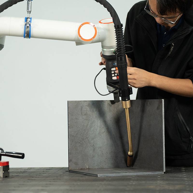
The 6-axis configuration is essential for the complex geometries encountered in chassis components. We observed that the primary advantage of the 6-axis system in automated welding is the ability to maintain a constant torch angle (work and travel angles) relative to the joint, regardless of the part’s orientation. During the field trial, we identified that a +/- 0.5mm deviation in TCP would result in significant undercut during high-speed MAG runs. In Stuttgart, we implemented a daily automated TCP check routine to ensure that the cobot’s sensors remained calibrated against the torch’s physical contact tip.
Integration with MAG Power Sources
The “High-Speed” aspect of this deployment relies on the digital communication between the cobot controller and the inverter power source. By using an EtherCAT interface, we achieved sub-millisecond response times for arc starting and crater fill sequences. This synergy is what defines modern automated welding: the machine doesn’t just move; it reacts to the arc voltage to maintain a consistent stick-out, even when the mild steel welding plates exhibit slight thermal warping.
3. Process Parameters for Mild Steel Welding
Mild steel welding is often underestimated. In a high-speed MAG environment, the window for a “perfect” weld is narrow. In our Stuttgart tests, we utilized a 1.2mm G3Si1 (ER70S-6) wire with an 82% Argon / 18% CO2 shielding gas mix.
Heat Input and Travel Speed Optimization
To achieve “high-speed” status, we pushed travel speeds to 80-100 cm/min. At these velocities, the fluid dynamics of the weld pool change. We observed a tendency for “humping” (bead instability) if the 6-Axis Collaborative Welder was not programmed with a slight leading torch angle.
Lesson Learned: A 10-degree push angle provided the best balance between penetration and surface wetting. Pulling the puddle at high speeds resulted in a concave profile that failed the Stuttgart site’s visual inspection (DIN EN ISO 5817 Level B).
Managing Mill Scale and Surface Contaminants
Automated systems are less forgiving than manual operators regarding surface prep. The S235JR mild steel arrived with varying levels of mill scale. While the 6-Axis Collaborative Welder can be programmed for multiple passes, the most efficient solution was found in the power source’s pulsing logic. By using a “High-Speed Pulse” mode, we achieved the necessary cleaning action to break through the oxide layer without slowing down the automated welding cycle.
4. Real-World Implementation: The Stuttgart Workshop Floor
Applying these technologies in Germany requires strict adherence to CE standards and ISO safety protocols. Because the system is a 6-Axis Collaborative Welder, we could eliminate the large footprint of safety light curtains in certain low-speed zones, though high-speed MAG cycles still required localized shielding to protect nearby personnel from UV radiation and spatter.
Jigging and Fixturing Challenges
A recurring issue in the field was the reliance on old manual jigs. Automated welding requires precision that exceeds what a manual welder can “compensate for on the fly.” We found that for mild steel welding on 6mm plates, the parts would shift up to 2mm due to thermal expansion. We had to redesign the fixtures with toggle clamps that allowed for thermal growth while maintaining the joint centerline. This is where the 6-axis flexibility proved vital; we could easily add a “search” routine to the cobot’s logic to find the edge of the plate before striking the arc.
5. Lessons Learned from the Field
Lesson 1: Cable Management is Kinetic Geometry
In a 6-axis system, the dress pack (the bundle of gas lines, wire liners, and power cables) is a point of failure. At the Stuttgart site, we experienced two wire-feed interruptions because the cobot’s 5th-axis rotation pinched the liner during a complex fillet weld.
Practical Fix: We moved to a “rotary union” style mounting at the wrist. When setting up a 6-Axis Collaborative Welder, the “air-cut” (moving the robot without welding) must be performed at full speed to ensure the cables do not snag or create excessive friction for the wire feeder.
Lesson 2: The Myth of “Set and Forget” in Automated Welding
Many engineers believe automated welding on mild steel welding projects is a static process. In reality, the wire batch, gas purity, and even the ambient temperature in the Stuttgart facility (which fluctuates between 15°C and 35°C seasonally) affect the arc. We implemented a “Parameter Offset” protocol where the lead welder can adjust the voltage by +/- 5% via the cobot’s tablet interface without needing to rewrite the program.
Lesson 3: Collaborative Safety vs. High-Speed Physics
While the robot is “collaborative,” the MAG process is not. The “Collaborative” aspect of the 6-Axis Collaborative Welder refers to the ease of programming and the force-limiting sensors during setup. During high-speed automated welding, the system must be treated with the same respect as a standard industrial robot. We learned that the “collaborative” stop-on-impact feature is great for setup, but it won’t prevent a burn if a technician enters the zone during a 100 cm/min MAG run.
6. Metallurgical and Quality Results
Post-implementation analysis of the S235JR components showed a 40% reduction in the Heat Affected Zone (HAZ) compared to manual MAG welding. This is a direct result of the higher travel speeds made possible by the 6-Axis Collaborative Welder. Cross-sectional macros revealed excellent fusion at the root, with no signs of porosity. The consistency of the automated welding path ensured that the “cold start” defects typically found in manual welding were eliminated through programmed “hot start” routines in the power source.
7. Conclusion
The Stuttgart field operation confirms that a 6-Axis Collaborative Welder is the most viable path for SMEs looking to adopt automated welding for mild steel welding. The synergy between the cobot’s ease of use and the high-speed MAG process allows for a significant increase in parts-per-hour without sacrificing the metallurgical integrity of the S235JR/S355J2 assemblies. However, success is predicated on rigorous TCP management, updated fixturing, and an understanding that the robot is only as good as the welding physics programmed into it. Moving forward, we recommend a “training-the-trainer” approach where manual welders are promoted to “Cobot Supervisors,” ensuring that the deep tribal knowledge of the Stuttgart workforce is digitized into the automation logic.
Report Compiled by: Senior Welding Engineer, Field Operations Division
Location: Stuttgart, Germany
Status: Commissioning Complete / Production Active
-


Cantilever Welding Robot solution
-


GF laser cutting machine
-

P3015 plasma cutting machine
-

LFP3015 Fiber Laser Cutter
-

pipe plasma cutting machine
-
LFH 4020 Fiber Laser Cutting Machine
-
LFP4020
-

gantry plasma air cutting machine
-

3D robot cutting machine
-

8 axis plasma cutting machine
-

5 axis plasma cutting machine
-

LT360 tube laser cutting machine
-

robot welding workstation
-

SF6060 fiber laser cutting machine
Advanced Fiber Laser Tube Processing Technology
Our CNC Fiber Laser Tube Cutting systems revolutionize metal fabrication by integrating high-precision cutting, punching, and profiling into a single automated workflow. Designed for versatility, this technology handles a wide array of profiles including Round, Square, Rectangular, and Oval tubes, as well as complex L-shaped and U-shaped channels.
- Precision Punching: High-speed hole punching with micron-level accuracy, eliminating the need for mechanical drilling or die-stamping.
- Complex Profiling: Advanced 3D pathing allows for intricate interlocking joints and specialized notch cuts, ideal for structural frames.
- High Material Efficiency: Intelligent nesting software minimizes scrap, reducing raw material costs across large production runs.
- Clean Finish: Delivers oxide-free, burr-free edges that require zero secondary grinding before welding.

Seamlessly processing multiple profiles with consistent precision.
Global Delivery & Logistics



From our high-tech manufacturing facility directly to your global site. PCL WeldCut ensures secure packaging, professional handling, and reliable international logistics to safeguard your equipment throughout the entire journey.