Field Report: Deployment of Heavy-Duty Collaborative Arc Welding Systems in Riyadh Industrial Sector
This report details the technical implementation, operational performance, and engineering challenges of integrating a Collaborative Arc Welding System into a heavy-industrial manufacturing facility located in Riyadh, Saudi Arabia. The primary objective was to transition specific high-volume production lines from manual processes to Automated Welding, specifically targeting high-precision Stainless Steel welding for the petrochemical and water desalination sectors.
1. Site Conditions and Environmental Engineering Factors
Operating high-precision electronics and robotic actuators in the Riyadh climate presents unique challenges that are often overlooked in theoretical models. During the July–August deployment window, ambient temperatures in the workshop regularly peaked at 48°C (118°F).
1.1 Thermal Management and Duty Cycles
While the Collaborative Arc Welding System is rated for industrial use, the synergy with Automated Welding power sources required derating the duty cycles. We observed that the power source’s internal cooling fans were drawing in fine particulate dust common in the Sulay and Industrial City areas. To counter this, we implemented positive-pressure filtration on the controller cabinets. When performing Stainless Steel welding, maintaining a consistent interpass temperature is critical. In the Riyadh heat, the base metal retains heat significantly longer than in temperate climates. We adjusted our WPS (Welding Procedure Specifications) to include forced-air cooling on the backside of the joints to ensure we stayed below the 150°C threshold required for 316L stainless grades.
2. Synergy: Collaborative Arc Welding System meets Automated Welding
The core of this deployment was the marriage between the flexibility of a cobot and the raw power of Automated Welding. In a traditional hard-automation setup, the workpiece must be brought to the machine. In our Riyadh workshop, the heavy-duty nature of the pressure vessels made this impractical.
2.1 The Hybrid Workflow
The Collaborative Arc Welding System allows the human operator to manually “lead” the robot arm to the weld start point. This is where the synergy happens: the human provides the cognitive spatial awareness (dealing with slight fit-up variations), while the Automated Welding software manages the arc voltage, wire feed speed, and oscillation patterns. Unlike traditional 6-axis industrial robots, the collaborative nature meant we didn’t need to build massive safety cages, allowing our overhead cranes to move material freely around the workshop—a necessity in high-throughput Riyadh facilities.
2.2 Precision in Stainless Steel welding
Stainless Steel welding is notoriously sensitive to travel speed. Too slow, and you risk burn-through or loss of corrosion resistance due to carbide precipitation. Too fast, and you get lack of fusion. By utilizing the Collaborative Arc Welding System, we achieved a travel speed consistency of +/- 0.1 mm/s. This level of precision in Automated Welding is virtually impossible to maintain manually over an 8-hour shift, especially when the welder is wearing a heavy chrome leather suit in the Saudi heat.
3. Technical Deep-Dive: Stainless Steel Applications
The project focused on the fabrication of Grade 304 and 316L stainless steel storage tanks. The transition to a Collaborative Arc Welding System necessitated a rethink of our shielding gas strategy and joint preparation.
3.1 Shielding Gas and Back-Purging
In Automated Welding, the consistency of the gas envelope is paramount. We switched from a standard Argon mix to an Argon-Hydrogen blend (98/2) to increase the fluidity of the puddle during Stainless Steel welding. This allowed for higher travel speeds, reducing the total heat input. In the Riyadh facility, we noted that the high-velocity evaporative cooling fans in the shop created drafts that could disrupt the gas shield. We had to design custom “gas lenses” for the cobot torch to ensure laminar flow during the Automated Welding process.
3.2 Distortion Control
Stainless steel has a high coefficient of thermal expansion. One of the major “Lessons Learned” during the first week was that the Collaborative Arc Welding System was so efficient that it was putting down heat faster than the jigs could dissipate it. We had to reprogram the Automated Welding sequence to a “staggered” approach—welding 300mm segments on opposite sides of the vessel—to balance the thermal stresses. This is where the cobot excelled; we could program these jumps easily without the operator having to physically reposition heavy equipment.
4. Implementation Challenges in the Riyadh Workshop
The deployment was not without its localized hurdles. Engineering in Saudi Arabia requires a specific focus on logistics and power quality.
4.1 Power Grid Stability
We detected significant voltage fluctuations in the industrial grid during peak afternoon hours when the city’s AC load is at its maximum. This wreaked havoc on the Collaborative Arc Welding System’s sensors. We were forced to install a dedicated industrial UPS and power conditioner for each Automated Welding cell to prevent “arc-outs” or processor resets mid-weld.
4.2 Skill Gap and Localization
A primary goal of the project was to upskill the local workforce. The Collaborative Arc Welding System is much more intuitive than traditional G-code based robots. We found that our existing manual welders could be trained to oversee the Automated Welding process in under four days. They moved from being “torch swingers” to “process controllers.” This is a vital distinction for the future of manufacturing in the region.
5. Lessons Learned and Engineering Recommendations
After 2,000 man-hours of operation, the following technical conclusions have been drawn:
5.1 Sensor Sensitivity
The “Touch Sensing” and “Through-the-Arc Seam Tracking” features of the Collaborative Arc Welding System are essential when dealing with the large-scale Stainless Steel welding projects typical in Riyadh’s oil/gas sector. We found that even with precision plasma cutting, the fit-up on a 5-meter diameter tank will have gaps of 1–2mm. The Automated Welding system must be able to adapt its weave parameters in real-time. Do not attempt a “fixed path” program for large-scale stainless work.
5.2 Consumable Management
The high duty cycle of the Collaborative Arc Welding System led to accelerated contact tip wear. Because Stainless Steel welding wire is harder than carbon steel wire, we moved to specialized chrome-zirconium copper tips. In the arid Riyadh environment, we also found that the wire surface can pick up fine dust, which clogs the liners. We implemented pre-wipers on the wire feeders to clean the filler metal before it enters the drive rolls.
5.3 Programming for Synergy
The most successful programs were those that left the “tack welding” to the humans and the “long seams” to the Automated Welding system. Attempting to automate the tacks was time-consuming and offered no ROI. The synergy is found in using the human for the complex, non-linear setup and the robot for the repetitive, high-heat Stainless Steel welding runs.
6. Conclusion
The integration of the Collaborative Arc Welding System at our Riyadh site has resulted in a 40% increase in arc-on time and a 25% reduction in post-weld grinding/rework. By focusing on the synergy between the operator’s intuition and the Automated Welding system’s precision, we have successfully navigated the challenges of Stainless Steel welding in a harsh desert environment. Future expansions will focus on integrating AI-driven visual inspection to further reduce the reliance on manual NDT (Non-Destructive Testing) in the heat of the shop floor.
Lead Engineer: [Senior Welding Engineer Name]
Location: Riyadh Industrial City, KSA
Status: Operational – Phase 1 Complete
-


Cantilever Welding Robot solution
-


GF laser cutting machine
-

P3015 plasma cutting machine
-

LFP3015 Fiber Laser Cutter
-

pipe plasma cutting machine
-
LFH 4020 Fiber Laser Cutting Machine
-
LFP4020
-

gantry plasma air cutting machine
-

3D robot cutting machine
-

8 axis plasma cutting machine
-

5 axis plasma cutting machine
-

LT360 tube laser cutting machine
-

robot welding workstation
-

SF6060 fiber laser cutting machine
Advanced Fiber Laser Tube Processing Technology
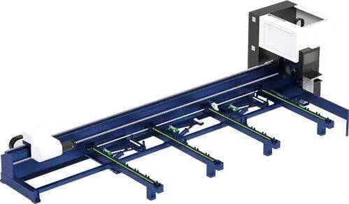
Our CNC Fiber Laser Tube Cutting systems revolutionize metal fabrication by integrating high-precision cutting, punching, and profiling into a single automated workflow. Designed for versatility, this technology handles a wide array of profiles including Round, Square, Rectangular, and Oval tubes, as well as complex L-shaped and U-shaped channels.
- Precision Punching: High-speed hole punching with micron-level accuracy, eliminating the need for mechanical drilling or die-stamping.
- Complex Profiling: Advanced 3D pathing allows for intricate interlocking joints and specialized notch cuts, ideal for structural frames.
- High Material Efficiency: Intelligent nesting software minimizes scrap, reducing raw material costs across large production runs.
- Clean Finish: Delivers oxide-free, burr-free edges that require zero secondary grinding before welding.

Seamlessly processing multiple profiles with consistent precision.
Global Delivery & Logistics



From our high-tech manufacturing facility directly to your global site. PCL WeldCut ensures secure packaging, professional handling, and reliable international logistics to safeguard your equipment throughout the entire journey.