Field Report: Deployment of Collaborative Arc Welding System in Bursa Heavy Industrial Sector
Project Overview and Site Context
This report details the technical implementation and performance validation of a high-payload Collaborative Arc Welding System at a heavy-machinery fabrication facility in Bursa, Turkey. The objective was to transition a significant portion of the structural chassis production from manual GMAW (Gas Metal Arc Welding) to a semi-autonomous workflow. The primary technical challenge involved Thick Plate Steel welding, specifically S355JR grade steel ranging from 15mm to 30mm in thickness.
Bursa serves as a critical hub for automotive and heavy duty industrial manufacturing. The local labor market, while skilled, faces increasing pressure to improve throughput without compromising the structural integrity of heavy-duty weldments. This deployment focused on integrating Automated Welding capabilities within a collaborative framework to allow human operators to manage complex jigging while the system handles the high-heat, high-duty-cycle deposition tasks.
Technical Specifications of the Collaborative Arc Welding System
The system deployed consists of a 10kg-payload collaborative robot arm integrated with a high-performance, water-cooled GMAW power source. Unlike traditional industrial robots, this Collaborative Arc Welding System utilizes sensitive force-torque sensors and simplified lead-through programming, which is essential for the high-mix, low-volume nature of Bursa’s heavy-duty equipment sector.
Power Source and Wire Feed Parameters
To handle Thick Plate Steel welding, we utilized a pulsed-spray transfer mode. The power source was calibrated to manage 320–380 Amps at a 100% duty cycle. We utilized 1.2mm ER70S-6 wire with an M21 shielding gas mix (82% Ar / 18% CO2). The synergy between the power source’s waveform control and the cobot’s motion profile allowed for a constant travel speed of 35-40 cm/min, significantly higher than manual averages for multi-pass fillets.
Integrating Automated Welding into Manual Workflows
The core success of this project relied on the synergy between Automated Welding and the existing workshop layout. In traditional automation, a “hard-tooled” cell would require significant floor space and safety fencing, which was not feasible in this specific Bursa facility due to the size of the workpieces (6-meter longitudinal beams).
By implementing a Collaborative Arc Welding System, we achieved a hybrid workflow. The operator performs the tack welding and initial fit-up. The cobot is then moved into position via a magnetic base or a simplified rail. The operator “teaches” the start and end points of the weld path, and the Automated Welding sequence takes over. This allows the welder to prep the next joint while the system executes a 1.5-meter continuous multi-pass weld, reducing idle time by approximately 45%.
Addressing the Challenges of Thick Plate Steel Welding
Welding 25mm to 30mm plate requires specialized joint preparation and thermal management. We employed a 60-degree V-groove preparation with a 2mm root face. The Collaborative Arc Welding System was programmed for a three-layer strategy: a root pass, two fill passes, and a weaving cap pass.
Heat Input and Interpass Temperature
One of the primary technical hurdles in Thick Plate Steel welding is managing the Heat Affected Zone (HAZ). During the Bursa trials, we noted that manual welders often struggle with consistency during long-duration passes, leading to localized overheating. The Automated Welding logic allowed us to program precise interpass cooling intervals. We utilized an infrared pyrometer integrated with the controller to ensure the interpass temperature did not exceed 200°C, preserving the mechanical properties of the S355JR steel.
Root Pass Consistency
The root pass on thick plate is notoriously difficult due to potential burn-through or lack of fusion. By using a “Touch-Sensing” routine integrated into the Collaborative Arc Welding System, the robot identifies the exact location of the plate edge before striking the arc. This compensates for any inconsistencies in the manual tacking process, ensuring the root pass is centered perfectly in the groove.
Synergy: Why the Collaborative Approach Works in Bursa
The heavy-duty workshops in Bursa often operate on a “Cellular Manufacturing” logic rather than “Assembly Line” logic. This is where the synergy between Collaborative Arc Welding System technology and Automated Welding becomes evident. A fully automated, non-collaborative robot is too rigid for a shop floor where the crane movement and jigging vary daily.
The collaborative system acts as a “power tool” rather than a “replacement.” The operator remains the lead technician, making real-time adjustments to torch angles or weave widths based on the fit-up gap, while the Automated Welding logic handles the precision of the arc length and the consistency of the travel speed. This partnership is vital for Thick Plate Steel welding, where a single mistake in a deep groove can require hours of grinding and rework.
Technical Lessons Learned and Field Observations
During the six-week implementation phase, several critical technical insights were documented:
1. Gas Shielding in Open Shop Environments
Many Bursa-based facilities are large, open-air structures. We found that even slight drafts compromised the gas shield during the Automated Welding process, leading to porosity in the thick plate fill passes. We had to implement localized “wind curtains” around the cobot base and increase the gas flow to 20 L/min. For Thick Plate Steel welding, porosity is an immediate fail on UT (Ultrasonic Testing), making this a high-priority fix.
2. Wire Stick-Out Management
In Automated Welding, maintaining a constant Contact Tip to Work Distance (CTWD) is crucial. On 30mm plates, as the weld groove fills up, the distance changes. We found that utilizing “Through-Arc Seam Tracking” (TAST) was necessary. The Collaborative Arc Welding System monitors the current variations as the torch weaves; if the current increases (indicating a shorter stick-out), the robot automatically adjusts its Z-axis height. This proved essential for maintaining penetration depth in deep grooves.
3. Grounding and Magnetic Arc Blow
Heavy steel plates act as massive heat sinks and can also generate magnetic fields that deflect the arc—a phenomenon known as arc blow. In Automated Welding, this can cause the bead to wander off-center. We learned that for Thick Plate Steel welding, multiple grounding points on the chassis were required to stabilize the arc. We positioned the grounds symmetrically relative to the cobot’s path to neutralize the magnetic field.
Performance Metrics and Quality Assurance
Post-implementation analysis showed a significant improvement in weld quality. All Thick Plate Steel welding samples passed 100% Visual Inspection (VT) and 20% Random Ultrasonic Testing (UT). The consistency provided by the Automated Welding sequence reduced the repair rate from 8% (manual) to less than 1.5%.
In terms of deposition rates, the Collaborative Arc Welding System achieved an average of 5.2 kg/hr, compared to the manual average of 3.1 kg/hr. This increase is not just due to travel speed, but the ability of the system to maintain a high duty cycle without operator fatigue, particularly during the grueling fill passes on heavy structural beams.
Conclusion and Recommendations
The deployment in Bursa confirms that the Collaborative Arc Welding System is a viable and superior alternative to purely manual processes for Thick Plate Steel welding. The key is not to view the system as a “set and forget” machine, but as a high-precision extension of the welder’s skill.
For future implementations in similar heavy-industrial environments, I recommend:
- Standardization of Groove Geometry: While the cobot can compensate for some variation, consistent CNC-milled or plasma-cut bevels greatly enhance the speed of Automated Welding.
- Operator Upskilling: Focus training on “Weld Path Optimization” rather than just “Robot Operation.” The best cobot operators are those who already understand the nuances of Thick Plate Steel welding.
- Adaptive Hardware: In Bursa’s variable ambient temperatures, ensuring a robust water-cooling system for the torch is non-negotiable for high-amperage Automated Welding.
This report concludes that the synergy of collaborative robotics and advanced arc control provides the necessary technical framework to meet the increasing demands of Turkey’s heavy-duty fabrication sector.
-


LT240S tube laser cutting machine
-
LT120S tube laser cutting machine
-
Sale

Tank Fillet Welding Machine
Original price was: $1,000.00.$900.00Current price is: $900.00. -
Sale

MAK100 tube laser cutting machine
Original price was: $5,500.00.$5,000.00Current price is: $5,000.00. -

portable plasma air cutting machine
$1,200.00 -

2in1 fiber laser cutting machine
-

Air cooling Laser welding machine
-

HF h beam laser cutting machine
-

LT240 laser cutting machine
-

Laser welding machine
-


Cobot Welding Station
-

Gantry welding robot solution
-

Tracked Wheeled AGV Welding robot
-

LFH6020 Fiber laser cutting machine
-
LFP6020
-

robotic welidng machine
Advanced Fiber Laser Tube Processing Technology
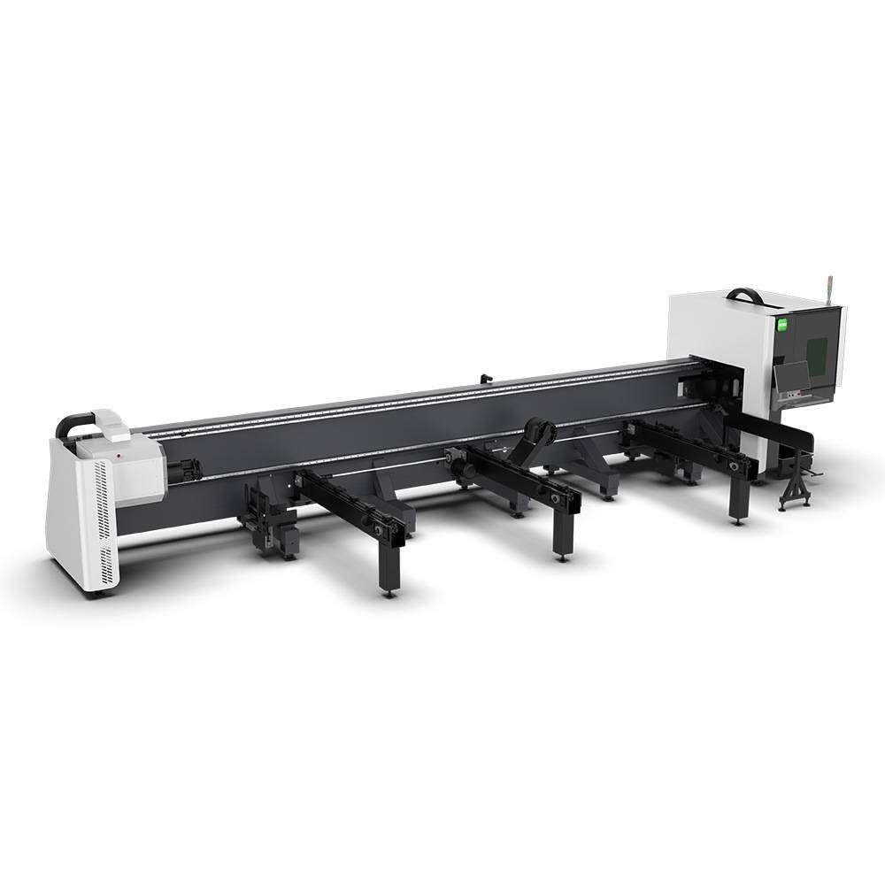
Our CNC Fiber Laser Tube Cutting systems revolutionize metal fabrication by integrating high-precision cutting, punching, and profiling into a single automated workflow. Designed for versatility, this technology handles a wide array of profiles including Round, Square, Rectangular, and Oval tubes, as well as complex L-shaped and U-shaped channels.
- Precision Punching: High-speed hole punching with micron-level accuracy, eliminating the need for mechanical drilling or die-stamping.
- Complex Profiling: Advanced 3D pathing allows for intricate interlocking joints and specialized notch cuts, ideal for structural frames.
- High Material Efficiency: Intelligent nesting software minimizes scrap, reducing raw material costs across large production runs.
- Clean Finish: Delivers oxide-free, burr-free edges that require zero secondary grinding before welding.

Seamlessly processing multiple profiles with consistent precision.
Global Delivery & Logistics



From our high-tech manufacturing facility directly to your global site. PCL WeldCut ensures secure packaging, professional handling, and reliable international logistics to safeguard your equipment throughout the entire journey.