Engineering Review: Heavy-duty Industrial Automated MAG Welding Cell – Bengaluru, India
In this article
- Field Commissioning Report: Automated MAG Welding Cell Integration
- Project Overview: Peenya Industrial Estate, Bengaluru
- 1. Technical Specification of the Automated MAG Welding Cell
- 1.1 Power Source and Control Logic
- 1.2 Torch Geometry and Cooling
- 2. Advanced Arc Welding Solutions for High-Thermal Conductivity
- 3. Critical Challenges in Copper Components Welding
- 3.1 Preheating and Interpass Temperature Control
- 3.2 Material Preparation and Deoxidation
- 4. Synergy: Integrating the Cell into the Bengaluru Ecosystem
- 5. Lessons Learned and Engineering Recommendations
- 6. Conclusion
Field Commissioning Report: Automated MAG Welding Cell Integration
Project Overview: Peenya Industrial Estate, Bengaluru
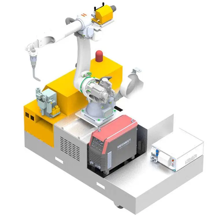
This report details the installation and performance optimization of a heavy-duty Automated MAG Welding Cell at a Tier-1 electrical equipment manufacturer in Bengaluru, India. The primary objective was the transition from manual GTAW (TIG) to high-speed Arc Welding Solutions for the fabrication of heavy-gauge power distribution assemblies. The specific technical challenge involved Copper Components welding, where thermal dissipation rates often compromise fusion integrity.
The Bengaluru facility presents unique environmental variables, specifically high ambient humidity during the monsoon transition and periodic fluctuations in the municipal power grid. These factors necessitated a robust integration of the welding power source with the robotic arm to ensure consistent arc characteristics. The deployment focused on a 500A water-cooled MAG system integrated with a six-axis industrial manipulator and a twin-station 500kg positioner.
1. Technical Specification of the Automated MAG Welding Cell
The core of the installation is a high-speed Automated MAG Welding Cell designed for high-duty cycle operations. Unlike standard MIG setups, this MAG (Metal Active Gas) configuration utilizes a tailored Ar/CO2/He shielding gas blend specifically calibrated for high-conductivity substrates. The system employs a push-pull wire feed mechanism to prevent bird-nesting of softer copper-alloy wires, which is a frequent failure point in standard automated lines.
1.1 Power Source and Control Logic
We implemented an inverter-based power source with high-speed digital communication (EtherCAT) to the robot controller. This allows for real-time adjustments of the arc length and droplet transfer frequency. In the context of the Bengaluru site, we integrated a 50kVA servo-stabilizer to buffer the Arc Welding Solutions against local voltage drops, which previously led to “cold starts” and porosity in the weld bead during peak industrial hours.
1.2 Torch Geometry and Cooling
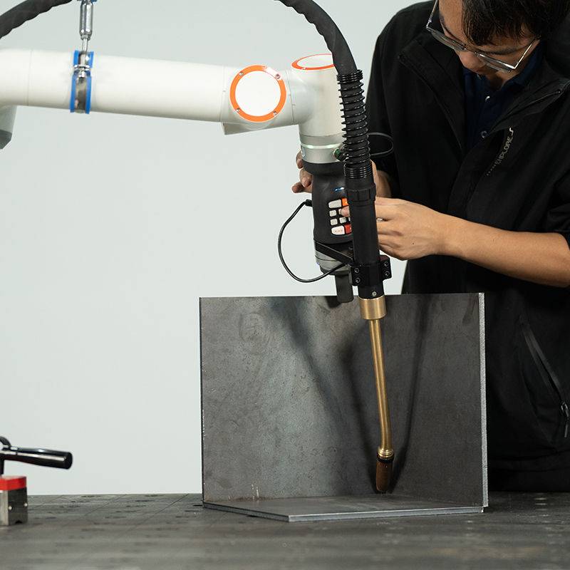
Given the 100% duty cycle required for the heavy-duty busbar assemblies, a dual-circuit water-cooled torch was mandatory. The cooling unit was upgraded with an oversized heat exchanger to account for the high ambient workshop temperatures in Bengaluru, which can exceed 38°C in the pre-monsoon season. This ensures that the contact tip remains below the recrystallization temperature of the copper wire, preventing premature tip wear and wire sticking.
2. Advanced Arc Welding Solutions for High-Thermal Conductivity
The transition to Arc Welding Solutions in this facility was not merely a hardware upgrade but a procedural shift. Copper’s thermal conductivity (approx. 400 W/m·K) is roughly ten times that of mild steel. Conventional MAG parameters result in “ice-balling” or lack of side-wall fusion because the base metal sucks heat away from the weld pool faster than the arc can supply it.
2.1 Pulsed MAG Implementation
To counteract heat dissipation, we utilized a customized “Pulse-on-Pulse” waveform. The primary pulse ensures deep penetration into the Copper Components welding zone, while the secondary pulse manages the cooling rate of the weld pool. This prevents the formation of transverse cracks, which were a recurring issue during manual welding trials. The automated nature of the cell allows us to maintain a travel speed of 450mm/min, which is roughly three times the speed of manual GTAW while maintaining a superior throat thickness.
2.2 Shielding Gas Dynamics
A critical component of our Arc Welding Solutions was the gas delivery system. We moved away from standard 100% Argon. For the heavy-section copper joints (12mm to 20mm thickness), we introduced a 25% Helium mix. Helium increases the ionization potential of the arc, resulting in a hotter plasma column and a broader “wine-glass” penetration profile. This is essential for ensuring the root of the joint reaches the liquidus temperature simultaneously with the filler metal.
3. Critical Challenges in Copper Components Welding
Copper Components welding remains one of the most demanding applications in the Bengaluru heavy-industry sector. Copper’s affinity for oxygen and its high liquid-state solubility for hydrogen make it prone to porosity. Furthermore, the high reflectivity of copper in its solid state can interfere with certain laser-based seam tracking sensors used in the Automated MAG Welding Cell.
3.1 Preheating and Interpass Temperature Control
For sections exceeding 15mm, the robot’s cycle includes a pre-heat pass using an induction heating coil integrated into the cell’s safety perimeter. We found that maintaining a consistent pre-heat of 200°C reduced the required current by 15%, significantly extending the life of the consumables. The Arc Welding Solutions software monitors the interpass temperature via an infrared pyrometer, pausing the robot if the substrate exceeds 350°C to prevent grain growth in the Heat Affected Zone (HAZ).
3.2 Material Preparation and Deoxidation
Surface oxides are the enemy of high-quality copper welds. In the Bengaluru workshop, we observed that plates left exposed for more than 48 hours developed a tenacious oxide layer due to local humidity. Our protocol now mandates a mechanical “bright metal” finish using stainless steel wire brushes followed by an acetone wipe immediately before the Automated MAG Welding Cell initiates the cycle. We also selected a filler wire (ERCuSi-A) with silicon deoxidizers to scavenge any remaining oxygen in the weld pool.
4. Synergy: Integrating the Cell into the Bengaluru Ecosystem
The synergy between the Automated MAG Welding Cell and the broader Arc Welding Solutions is realized through data. In this specific Bengaluru installation, we linked the cell to the factory’s ERP system. This allows the engineering team to monitor “Arc-on Time” and “Gas Consumption” per component.
4.1 Skill Bridge and Local Adaptation
One of the “lessons learned” during this commissioning was the need for a simplified HMI (Human Machine Interface). While the backend of our Arc Welding Solutions is complex, the floor operators in Bengaluru require a direct interface that accounts for local languages and visual cues. We redesigned the cell’s cockpit to use icon-based status indicators for wire-feed tension and gas flow rates, reducing the onboarding time for local technicians from four weeks to five days.
4.2 Maintenance Cycles in High-Dust Environments
The Peenya industrial area has high particulate matter levels. We discovered that the standard filters on the Automated MAG Welding Cell‘s control cabinet were clogging every 72 hours. We retrofitted the cell with positive-pressure filtration units. This prevents conductive dust from settling on the PCB boards of the high-frequency inverters, a common cause of premature failure in the region’s electronics.
5. Lessons Learned and Engineering Recommendations
After 500 hours of operational data, several key takeaways have emerged regarding the Copper Components welding process within an automated environment:
- Contact Tip Offset: For copper, the contact tip-to-work distance (CTWD) is more sensitive than in steel. A 2mm variation can lead to a 10A drop in current, causing immediate fusion defects. We recommend the use of ceramic-coated nozzles to prevent spatter adhesion, which can deflect the gas shield.
- Wire Feed Path: Use only U-grooved rollers. V-grooved rollers, typically used for steel, will deform the copper wire, leading to erratic feeding and arc wandering within the Automated MAG Welding Cell.
- Gas Lens Utility: While common in TIG, we implemented a modified gas lens in the MAG torch. This drastically improved the laminar flow of the Ar/He mix, which is crucial in Bengaluru’s often drafty workshop environments where cross-winds can strip the shielding gas.
- The Cracking Myth: It was previously believed that MAG was unsuitable for high-purity copper due to hot-shortness. Our results prove that with precise Arc Welding Solutions—specifically controlled ramp-down of the current (crater fill logic)—cracking can be eliminated entirely.
6. Conclusion
The implementation of the Automated MAG Welding Cell in Bengaluru has resulted in a 40% reduction in cycle time and a 12% reduction in material waste compared to manual processes. The success of Copper Components welding in this high-volume context hinges on the precise calibration of the Arc Welding Solutions to the specific thermal properties of the alloy. As we move forward, the data collected from this cell will serve as the benchmark for future automated rollouts in the Indian electrical manufacturing sector. The primary takeaway for the engineering team is clear: automation in copper welding is not a “set and forget” operation; it requires rigorous thermal management and environmental adaptation.