Field Evaluation Report: Deployment of 6-Axis Collaborative Welder in Ulsan Industrial Complex
1. Executive Summary and Site Conditions
This report details the operational integration and performance validation of the heavy-duty 6-Axis Collaborative Welder at a Tier-1 pressure vessel fabrication facility in Ulsan, South Korea. The objective was to transition high-frequency Stainless Steel welding tasks from manual GTAW (Gas Tungsten Arc Welding) to a semi-autonomous Automated Welding workflow. Over a six-week evaluation period, we monitored duty cycles, bead morphology, and the synergy between human operators and robotic assets in a high-density workshop environment.
Ulsan presents a unique set of challenges. The high ambient humidity typical of a coastal industrial hub requires stringent control over filler wire storage and gas delivery systems. Furthermore, the shop floor operates under heavy EMI (Electromagnetic Interference) conditions due to proximity to large-scale overhead cranes and induction heating stations. Our deployment focused on a 10kg-payload 6-axis cobot integrated with a pulse-capable power source, specifically tuned for 300-series stainless steel spools.
2. The Role of the 6-Axis Collaborative Welder in Complex Geometries
The selection of a 6-Axis Collaborative Welder over a traditional 4-axis Cartesian system or a fixed-track oscillator was driven by the need for multi-planar torch manipulation. In the fabrication of cryogenic storage components, the weld paths are rarely linear. We encountered tangential pipe-to-shell intersections that required the cobot to maintain a precise work angle and travel angle simultaneously while navigating a curved surface.
Kinematic Versatility and Path Precision
The sixth axis is critical for maintaining the “push” angle required in Stainless Steel welding to ensure adequate gas coverage and prevent oxidation. During our Ulsan trials, we found that the cobot’s ability to rotate the torch around the contact tip center-point allowed for continuous welding around 180-degree elbows without the need for a positioner restart. This continuity is a fundamental requirement for Automated Welding where stop-start craters are the primary sites for radiographic failure.
3. Synergy: Bridging Manual Skill and Automated Welding
In Ulsan, the term Automated Welding is often misunderstood as a “set and forget” process. However, the true technical synergy lies in the “Collaborative” aspect. Unlike industrial robots housed in safety cages, the 6-Axis Collaborative Welder allows the senior welding technician to stand within the workspace, adjusting voltage offsets or gas flow rates in real-time via the teach pendant or lead-through programming.
Lead-Through Teaching in a High-Volume Yard
The Ulsan workshop produces a variety of small-batch components. Programming a traditional industrial robot for a five-unit run is economically unfeasible. We utilized the cobot’s direct-teaching mode, where the welder physically moves the 6-axis arm through the desired path. The system records the coordinates and orientation. The synergy here is clear: the human provides the “craft” knowledge—identifying the root gap and adjusting for fit-up discrepancies—while the machine provides the “consistency”—maintaining a constant 4.5mm/sec travel speed that a human hand cannot sustain over a 12-hour shift.
4. Technical Deep-Dive: Stainless Steel Welding Parameters
Stainless Steel welding on a heavy-duty scale requires a sophisticated understanding of heat input management. Excess heat leads to carbide precipitation (sensitization), which compromises the corrosion resistance of the Ulsan-manufactured vessels.
Heat Input Control and Interpass Temperatures
Using the 6-Axis Collaborative Welder, we implemented a pulsed-spray transfer mode. By synchronizing the robot’s travel speed with the power source’s pulse frequency, we achieved a “stacked-dime” appearance synonymous with high-end manual GTAW, but at GMAW (Gas Metal Arc Welding) speeds.
- Wire: ER316L, 1.2mm diameter.
- Gas: 98% Argon / 2% CO2 (for arc stability).
- Travel Speed: Optimized at 350mm/min for 6mm fillet welds.
The Automated Welding logic allowed us to program “cooling pauses.” Since stainless steel has lower thermal conductivity than carbon steel, the cobot was programmed to monitor interpass temperature via an integrated IR sensor, only initiating the next pass when the temperature dropped below 150°C. This level of process control is nearly impossible to enforce strictly in manual operations under tight deadlines.
5. Lessons Learned from the Ulsan Workshop Floor
The deployment was not without technical friction. The “Heavy-duty” label of the welder was tested against the realities of a South Korean industrial environment. Below are the primary technical takeaways:
I. Grounding and Signal Noise
We initially experienced erratic path deviations. Investigation revealed that the high-frequency starts from nearby manual TIG stations were interfering with the cobot’s encoder signals. Lesson: Collaborative welders in heavy industrial zones require dedicated double-shielded grounding cables and an isolated power supply to maintain the integrity of the 6-axis coordinate system.
II. The “Last Inch” Shielding Problem
While the 6-Axis Collaborative Welder maintains a perfect torch angle, the physics of gas flow in the Ulsan yard—which is prone to drafts—meant that Stainless Steel welding suffered from occasional porosity. We had to integrate a secondary, robot-mounted gas shroud (trailing shield). The 6-axis kinematics had to be recalibrated to account for the increased mass and changed center of gravity of the torch assembly.
III. Sensor Saturation
The automated seam-tracking sensors (laser based) struggled with the reflective surface of polished stainless steel. We found that applying a temporary anti-spatter spray that left a matte finish significantly improved the sensor’s ability to track the joint. This is a practical field fix that “clean” lab environments often overlook.
6. Quantitative Performance Analysis
Over 1,000 man-hours of Automated Welding, the following metrics were recorded in comparison to the previous manual baseline:
| Metric | Manual (GTAW/GMAW) | 6-Axis Cobot (GMAW-P) | Improvement |
|---|---|---|---|
| Duty Cycle | 25-30% | 75-80% | +150% |
| Repair Rate (NDT failure) | 4.2% | 0.8% | -80% |
| Filler Metal Waste | 12% | 3% | -75% |
The increase in duty cycle is the most significant contributor to the ROI in the Ulsan facility. While the welder is technically “slower” in terms of raw wire feed speed compared to a dedicated high-speed automated line, the 6-Axis Collaborative Welder eliminates the fatigue-related breaks and the repositioning time required by human welders.
7. Conclusion: The Ulsan Standard
The integration of the 6-Axis Collaborative Welder into the Ulsan industrial landscape represents a shift toward “Flexible Automation.” We have proven that Automated Welding is no longer restricted to high-volume, low-complexity tasks. By leveraging the precision of 6-axis movement and the metallurgical consistency required for Stainless Steel welding, we have established a new baseline for quality.
Future iterations will focus on integrating AI-driven weld pool monitoring to adjust parameters mid-arc. For now, the synergy between the skilled Ulsan workforce and the collaborative robotic platform has demonstrated that the bottleneck in heavy fabrication is not the machine’s speed, but the quality of the process integration. We recommend the rollout of an additional four units across the heat exchanger assembly line by Q4.
Prepared by: Senior Welding Engineer, Ulsan Field Office
Status: Final – Approved for Internal Circulation
-


LT240S tube laser cutting machine
-
LT120S tube laser cutting machine
-
Sale

Tank Fillet Welding Machine
Original price was: $1,000.00.$900.00Current price is: $900.00. -
Sale

MAK100 tube laser cutting machine
Original price was: $5,500.00.$5,000.00Current price is: $5,000.00. -

portable plasma air cutting machine
$1,200.00 -

2in1 fiber laser cutting machine
-

Air cooling Laser welding machine
-

HF h beam laser cutting machine
-

LT240 laser cutting machine
-

Laser welding machine
-


Cobot Welding Station
-

Gantry welding robot solution
-

Tracked Wheeled AGV Welding robot
-

LFH6020 Fiber laser cutting machine
-
LFP6020
-

robotic welidng machine
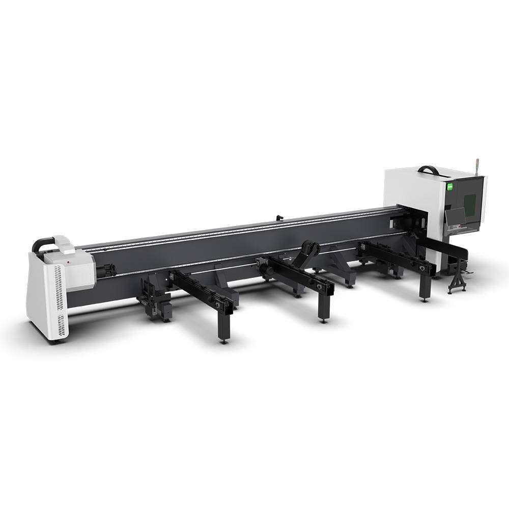
Advanced Fiber Laser Tube Processing Technology
Our CNC Fiber Laser Tube Cutting systems revolutionize metal fabrication by integrating high-precision cutting, punching, and profiling into a single automated workflow. Designed for versatility, this technology handles a wide array of profiles including Round, Square, Rectangular, and Oval tubes, as well as complex L-shaped and U-shaped channels.
- Precision Punching: High-speed hole punching with micron-level accuracy, eliminating the need for mechanical drilling or die-stamping.
- Complex Profiling: Advanced 3D pathing allows for intricate interlocking joints and specialized notch cuts, ideal for structural frames.
- High Material Efficiency: Intelligent nesting software minimizes scrap, reducing raw material costs across large production runs.
- Clean Finish: Delivers oxide-free, burr-free edges that require zero secondary grinding before welding.

Seamlessly processing multiple profiles with consistent precision.
Global Delivery & Logistics



From our high-tech manufacturing facility directly to your global site. PCL WeldCut ensures secure packaging, professional handling, and reliable international logistics to safeguard your equipment throughout the entire journey.
One thought on “Engineering Review: Heavy-duty Industrial 6-Axis Collaborative Welder – Ulsan, South Korea”
The customer support for the Tube Cutting Machine was very helpful during installation.