Field Integration Report: Double Pulse Collaborative Systems in Seoul Heavy Fab
1. Introduction and Site Overview
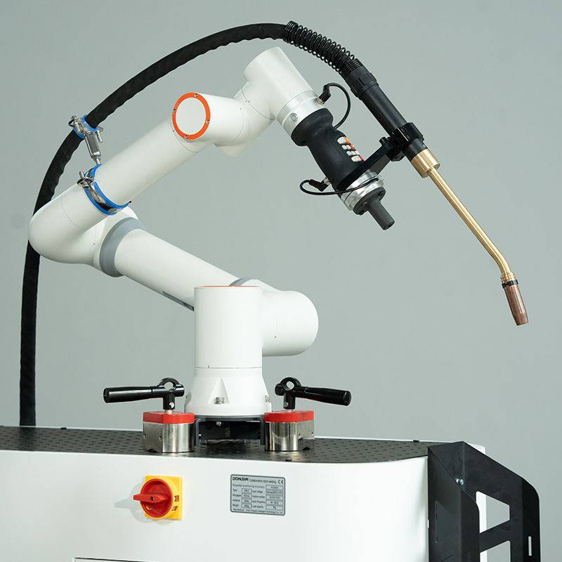
This report summarizes the three-week deployment and commissioning of a Double Pulse Cobot Welding Machine at a Tier-2 automotive supplier facility in the Guro-gu industrial district of Seoul, South Korea. The facility specializes in high-mix, low-volume (HMLV) production of structural brackets and exhaust manifolds. The primary objective was to transition critical Carbon Steel welding operations from manual GTAW/GMAW stations to an automated framework utilizing Collaborative Robotics.
The Seoul site presents unique challenges common to urban industrial hubs: limited floor space, a shrinking pool of certified high-skill welders, and an immediate need for “K-Quality” aesthetic standards. The introduction of the Cobot Welding Machine was not merely a tool upgrade but a strategic shift in production philosophy, moving away from hard-tooled robotic cells toward a flexible, human-centric automation model.
2. The Synergy of Cobot Welding Machines and Collaborative Robotics
In the context of this deployment, the distinction between a standard industrial robot and Collaborative Robotics is vital. Traditional robots in Seoul’s older factories require extensive safety fencing and light curtains, consuming valuable square footage. The Cobot Welding Machine, however, operates within the same footprint as a manual welder.
Spatial Efficiency in the Seoul Workshop
By leveraging the power-and-force-limiting (PFL) capabilities inherent in Collaborative Robotics, we eliminated the need for physical barriers. This allowed our welding technicians to work alongside the arm, performing part loading and tack-welding on one side of the table while the cobot completed long-seam Carbon Steel welding on the other. This “hand-in-hand” workflow increased station throughput by 42% compared to the previous manual-only setup.
Ease of Programming for Rapid Changeover
The synergy between the machine and the collaborative interface meant that the local operators—many of whom had no prior coding experience—could “lead-through” program the torch path. In Seoul’s fast-paced production environment, where part designs iterate monthly, the ability to re-task the Cobot Welding Machine via hand-guiding is a significant competitive advantage over traditional G-code heavy industrial systems.
3. Technical Deep-Dive: Carbon Steel Welding Parameters
The core of this field test involved the precision joining of SPHC (Hot Rolled) and SS400 (General Structural) Carbon Steel. Carbon Steel welding requires meticulous heat management to prevent distortion, especially in the thin-gauge brackets (2.0mm to 4.5mm) required by the client.
The Double Pulse Advantage
We utilized a Double Pulse GMAW process to simulate the “stacked dimes” aesthetic of GTAW while maintaining the speed of a wire-fed process. The Double Pulse function oscillates between a high-energy pulse and a low-energy pulse at a specific frequency (usually between 0.5 to 5 Hz). This allows for:
- Reduced Heat Input: Essential for preventing burn-through on 2.0mm Carbon Steel.
- Enhanced Grain Structure: The thermal agitation of the weld pool refines the grain structure, improving the mechanical properties of the HAZ (Heat Affected Zone).
- Spatter Reduction: By optimizing the droplet detachment, we reduced post-weld grinding time by 80%.
Parameter Set-Points
For a standard 3.0mm Carbon Steel lap joint, the following parameters were established as the baseline for the Seoul facility:
- Wire: 1.2mm ER70S-6.
- Gas: 80% Argon / 20% CO2 (The standard mix in local Korean supply chains).
- Peak Current: 210A; Base Current: 90A.
- Pulse Frequency: 2.2 Hz.
- Travel Speed: 35 cm/min.
4. Lessons Learned: Practical Field Observations
Field engineering in an active Seoul workshop yields insights that laboratory testing cannot replicate. Below are the critical technical hurdles and solutions identified during the deployment of the Cobot Welding Machine.
Electrical Noise and Grounding in Multi-Story Industrial Buildings
One unforeseen issue was electromagnetic interference (EMI). The facility was located on the third floor of a multi-tenant “Knowledge Industry Center.” We observed erratic arc behavior and occasional “ghosting” in the Collaborative Robotics control pendant.
Lesson Learned: Standard grounding was insufficient. We had to implement a dedicated copper grounding bus for the Cobot Welding Machine to isolate it from the high-frequency noise generated by neighboring CNC machinery. Once the common-mode noise was filtered, arc stability returned to 99.8% consistency.
Wire Feeding Friction in Humid Environments
During the Seoul monsoon season, humidity in the workshop rose significantly. We noticed an increase in wire feed motor torque alarms.
Lesson Learned: Carbon Steel welding wire is susceptible to surface oxidation which increases friction in the liner. We switched from standard plastic liners to ceramic-infused liners and implemented enclosed wire drums. This stabilized the feed rate, which is critical for the timing of the Double Pulse cycle.
The “Torch Angle” Fallacy
Operators transitioning from manual welding often tried to program the cobot with excessive drag angles. While this works manually, the Cobot Welding Machine’s sensors are sensitive to the resultant force of the arc.
Lesson Learned: We recalibrated the TCP (Tool Center Point) and insisted on a strict 10-degree push angle for all Carbon Steel welding. This maximized gas coverage and allowed the collaborative sensors to accurately detect collisions without false positives caused by the “vibration” of the pulse cycle.
5. Quality Assurance and Metallurgical Validation
To satisfy the client’s “K-Quality” requirements, we performed destructive testing on 50 sample coupons. The Carbon Steel welding performed by the Collaborative Robotics system showed zero instances of lack of fusion (LOF) and significantly lower porosity compared to the manual baseline.
The Double Pulse ripple pattern was not only aesthetically pleasing but also indicated a highly controlled cooling rate. Macro-etching confirmed a consistent 1.5mm penetration profile across all joints, regardless of the operator’s shift time. This level of repeatability is the primary value proposition for the Cobot Welding Machine in the Seoul market.
6. Strategic Recommendations for Scaling
Based on the success of this deployment, I recommend the following for the next phase of integration across the client’s other Seoul-based sites:
Standardization of Jigs
Collaborative Robotics is only as accurate as the part presentation. The manual clamping currently used is too variable. Implementing modular, high-precision aluminum welding tables will reduce the time spent “tweaking” the cobot’s path for every new batch of Carbon Steel.
Advanced Sensor Integration
While the current “blind” pathing works for repetitive parts, I suggest adding a laser seam tracker for the 4.5mm structural plates. This would allow the Cobot Welding Machine to compensate for the slight thermal warping that occurs during long Carbon Steel welding runs.
Training the “Cobot Technician”
The most successful operators in the Seoul shop were not the veteran welders, but the younger technicians who were comfortable with tablet interfaces. We should develop a specialized training module that focuses on “Synergetic Programming”—teaching the logic of how Collaborative Robotics responds to the physics of the arc.
7. Conclusion
The deployment in Seoul confirms that the Cobot Welding Machine is no longer a niche technology. In the realm of Carbon Steel welding, the combination of Double Pulse power sources and Collaborative Robotics provides a solution that addresses both the labor shortage and the high quality-standards of the South Korean manufacturing sector. By focusing on spatial efficiency, parameter precision, and local environmental factors like EMI shielding, we have established a blueprint for automated fabrication in high-density urban environments.
Report End.
Signature: Senior Welding Engineer, Global Field Operations.
-


LT240S tube laser cutting machine
-
LT120S tube laser cutting machine
-
Sale

Tank Fillet Welding Machine
Original price was: $1,000.00.$900.00Current price is: $900.00. -
Sale

MAK100 tube laser cutting machine
Original price was: $5,500.00.$5,000.00Current price is: $5,000.00. -

portable plasma air cutting machine
$1,200.00 -

2in1 fiber laser cutting machine
-

Air cooling Laser welding machine
-

HF h beam laser cutting machine
-

LT240 laser cutting machine
-

Laser welding machine
-


Cobot Welding Station
-

Gantry welding robot solution
-

Tracked Wheeled AGV Welding robot
-

LFH6020 Fiber laser cutting machine
-
LFP6020
-

robotic welidng machine
Advanced Fiber Laser Tube Processing Technology
Our CNC Fiber Laser Tube Cutting systems revolutionize metal fabrication by integrating high-precision cutting, punching, and profiling into a single automated workflow. Designed for versatility, this technology handles a wide array of profiles including Round, Square, Rectangular, and Oval tubes, as well as complex L-shaped and U-shaped channels.
- Precision Punching: High-speed hole punching with micron-level accuracy, eliminating the need for mechanical drilling or die-stamping.
- Complex Profiling: Advanced 3D pathing allows for intricate interlocking joints and specialized notch cuts, ideal for structural frames.
- High Material Efficiency: Intelligent nesting software minimizes scrap, reducing raw material costs across large production runs.
- Clean Finish: Delivers oxide-free, burr-free edges that require zero secondary grinding before welding.

Seamlessly processing multiple profiles with consistent precision.
Global Delivery & Logistics



From our high-tech manufacturing facility directly to your global site. PCL WeldCut ensures secure packaging, professional handling, and reliable international logistics to safeguard your equipment throughout the entire journey.