Field Engineering Report: Implementation of 6-Axis Collaborative Welder for Copper Components in Chonburi Industrial Sector
1. Project Overview and Site Conditions
This report details the commissioning and optimization of a 6-Axis Collaborative Welder (Cobot) integrated with a high-frequency double-pulse power source at a Tier-1 automotive electronics facility in Chonburi, Thailand. The primary objective was the transition from manual TIG processes to Automated Welding of high-purity copper components welding, specifically heavy-duty busbars and cooling plates.
The Chonburi environment presents unique challenges, primarily high ambient humidity (averaging 75-85%) and fluctuating grid stability within the industrial estate. These factors necessitated specific adjustments to the shielding gas delivery and the electrical isolation of the 6-axis collaborative welder to prevent porosity and arc instability.
2. The Synergy: 6-Axis Collaborative Welder and Automated Welding
The integration of a 6-Axis Collaborative Welder into an automated welding workflow represents a significant shift from traditional industrial robotics. In the Chonburi workshop, floor space is at a premium. Unlike traditional robots requiring extensive safety caging, the collaborative nature of the 6-axis arm allowed us to integrate the station directly into the existing assembly line.
2.1 Kinematic Flexibility
The 6-axis configuration is critical for copper components welding due to the complex geometries of the busbars. We utilized the full range of motion—specifically the J5 and J6 axes—to maintain a consistent torch angle of 15 degrees lead in tight radii. This precision is unattainable with 3 or 4-axis linear systems. The synergy here lies in the “lead-through programming” capability; local Thai technicians were able to hand-guide the robot to define Tool Center Points (TCP), which significantly reduced the downtime usually associated with automated welding trajectory programming.
2.2 Process Consistency
In automated welding, the repeatability of the 6-axis arm (rated at ±0.05mm) eliminates the “Monday morning” variance seen in manual operators. When dealing with copper’s high thermal conductivity, even a 2mm deviation in arc length can result in a lack of fusion. The 6-axis collaborative welder ensures that the arc length remains constant regardless of the operator’s skill level, stabilizing the heat input across the entire weldment.
3. Technical Deep Dive: Copper Components Welding Challenges
Copper components welding is notoriously difficult due to the material’s thermal diffusivity, which is approximately 10 to 100 times higher than that of structural steel. During our field tests in Chonburi, we identified that traditional constant-voltage (CV) MIG resulted in either excessive “pile-up” at the start of the weld or catastrophic burn-through at the end as the heat built up.
3.1 The Double Pulse Solution
To overcome this, we deployed a Double Pulse waveform. This involves a primary high-frequency pulse to ensure penetration and a secondary low-frequency pulse to agitate the puddle and control the cooling rate. This technique is essential for the automated welding of copper because it mimics the “stack of dimes” aesthetic and metallurgical integrity of TIG but at four times the travel speed. By syncing the 6-axis collaborative welder‘s travel speed with the pulse frequency, we achieved a refined grain structure in the heat-affected zone (HAZ).
3.2 Managing Thermal Sink
In Chonburi’s high-volume environment, we learned that pre-heating copper to 200°C was necessary for components over 6mm thick. The 6-axis collaborative welder was programmed with a “dwell time” at the start of the path to allow the double-pulse arc to establish a sufficient molten pool before initiating movement. This “hot start” logic is a critical component of automated welding for high-conductivity metals.
4. Lessons Learned: Field Observations from Chonburi
4.1 Atmospheric Interference and Gas Shielding
The humidity in Chonburi caused immediate issues with hydrogen-induced porosity in the copper welds. We initially used a standard Argon shield, but the results were inconsistent.
Lesson: We switched to a 75% Helium / 25% Argon mix. The higher ionization potential of Helium provided the additional heat required for copper components welding, while the 6-axis arm’s precise motion allowed us to use a narrower gas shroud, reducing gas consumption by 15% compared to manual setups.
4.2 Wire Feeding Dynamics
Copper wire is soft and prone to bird-nesting. In an automated welding setup, any friction in the liner stops the line.
Lesson: We implemented a push-pull torch system directly on the 6th axis of the collaborative welder. We also replaced standard steel liners with Teflon (PTFE) liners. Senior engineers must ensure that the 6-axis arm’s cable management system does not create sharp bends (less than 300mm radius) during high-angle maneuvers, as this induces wire feed fluctuations that ruin the double-pulse synergy.
4.3 Collaborative Safety and Sensors
The “Collaborative” aspect was tested when a technician inadvertently entered the workspace to check a fixture. The 6-axis collaborative welder‘s force-torque sensors triggered a Category 0 stop.
Lesson: While the robot is safe, the arc and the UV radiation are not. We had to install localized arc-flash curtains that the 6-axis arm could move behind. The synergy between automated welding and human proximity requires more than just robot safety; it requires process safety (shroud-integrated fume extraction and UV shielding).
5. Optimization of the Automated Welding Workflow
The success of automated welding in the Chonburi plant was ultimately measured by cycle time reduction. Manual welding of a complex copper cooling manifold took 14 minutes, including cooling breaks. The 6-axis collaborative welder reduced this to 3 minutes and 20 seconds.
5.1 Tool Center Point (TCP) Calibration
We found that because copper reflects high amounts of IR radiation, the torch neck on the 6-axis collaborative welder would slightly expand over an 8-hour shift. This expansion shifted the TCP by nearly 0.8mm. We implemented an automated “TCP Check” station where the robot touches a reference probe every 50 cycles to re-calibrate its coordinates. This is a mandatory step for high-precision copper components welding.
5.2 Double Pulse Tuning Parameters
For C11000 copper, our optimized settings were:
- Peak Current: 320A
- Base Current: 140A
- Pulse Frequency: 1.8 Hz to 2.5 Hz
- Duty Cycle: 40%
These parameters, executed by the 6-axis collaborative welder, ensured that the weld bead had sufficient “wetting” at the toes, preventing the cold-lap issues prevalent in automated welding of non-ferrous metals.
6. Conclusion and Recommendations
The deployment in Chonburi proves that a 6-axis collaborative welder is no longer just a tool for light-gauge steel; it is a robust solution for the demanding niche of copper components welding. The key to success is not just the robot itself, but the integration of double-pulse power management and a deep understanding of copper’s thermal properties.
Final Engineering Recommendations:
- Climate Control: In Chonburi, always use a refrigerated compressed air dryer for the pneumatic components of the automated welding jigging to prevent moisture from entering the weld zone.
- Grounding: Use dedicated copper grounding straps for the workpiece, as the 6-axis collaborative welder‘s internal electronics are sensitive to the high-frequency “noise” generated by double-pulse arcs.
- Training: Focus local training on “Path Offsetting” rather than just “Teaching,” allowing operators to adjust for batch-to-batch variations in copper plate dimensions.
The synergy of these technologies has moved the Chonburi facility from a 65% first-pass yield to 98.2%, validating the investment in high-end automated welding systems.
-


LT240S tube laser cutting machine
-
LT120S tube laser cutting machine
-
Sale

Tank Fillet Welding Machine
Original price was: $1,000.00.$900.00Current price is: $900.00. -
Sale

MAK100 tube laser cutting machine
Original price was: $5,500.00.$5,000.00Current price is: $5,000.00. -

portable plasma air cutting machine
$1,200.00 -

2in1 fiber laser cutting machine
-

Air cooling Laser welding machine
-

HF h beam laser cutting machine
-

LT240 laser cutting machine
-

Laser welding machine
-


Cobot Welding Station
-

Gantry welding robot solution
-

Tracked Wheeled AGV Welding robot
-

LFH6020 Fiber laser cutting machine
-
LFP6020
-

robotic welidng machine
Advanced Fiber Laser Tube Processing Technology
Our CNC Fiber Laser Tube Cutting systems revolutionize metal fabrication by integrating high-precision cutting, punching, and profiling into a single automated workflow. Designed for versatility, this technology handles a wide array of profiles including Round, Square, Rectangular, and Oval tubes, as well as complex L-shaped and U-shaped channels.
- Precision Punching: High-speed hole punching with micron-level accuracy, eliminating the need for mechanical drilling or die-stamping.
- Complex Profiling: Advanced 3D pathing allows for intricate interlocking joints and specialized notch cuts, ideal for structural frames.
- High Material Efficiency: Intelligent nesting software minimizes scrap, reducing raw material costs across large production runs.
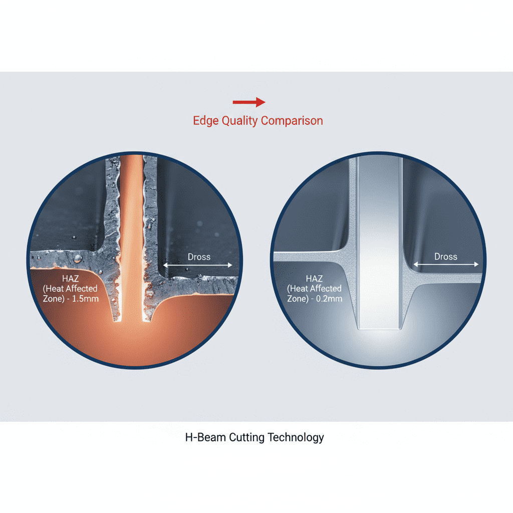
- Clean Finish: Delivers oxide-free, burr-free edges that require zero secondary grinding before welding.

Seamlessly processing multiple profiles with consistent precision.
Global Delivery & Logistics



From our high-tech manufacturing facility directly to your global site. PCL WeldCut ensures secure packaging, professional handling, and reliable international logistics to safeguard your equipment throughout the entire journey.