Field Report: Deployment of High-Amperage MAG Cobot Systems – Sao Paulo Industrial Hub
1. Executive Summary: Operational Overview
This report details the technical commissioning and field performance of a high-duty cycle MAG Cobot Welder integrated into the existing Arc Welding Solutions framework at a heavy-tier fabrication facility in the Guarulhos district, Sao Paulo. The objective was to transition from manual GMAW (Gas Metal Arc Welding) to a semi-automated collaborative environment to achieve consistent deep penetration on ASTM A36 structural steel, while simultaneously prepping the cell for upcoming Titanium welding contracts in the aerospace sector.
Sao Paulo’s industrial environment presents specific challenges: high ambient humidity (averaging 75-80%) and fluctuating power grid stability. Over a 30-day trial, we focused on the synergy between the robotic arm’s path precision and the power source’s waveform control to mitigate these variables.
2. Technical Integration: MAG Cobot Welder & Arc Welding Solutions
2.1 Synergic Waveform and Penetration Depth
The core of the deployment involved a 400-amp water-cooled MAG Cobot Welder. Unlike standard industrial robots, the cobot’s ability to operate in close proximity to human technicians allowed for real-time adjustments of the “Arc Sense” parameters. In the Sao Paulo facility, we implemented a modified spray transfer mode. To achieve the required 8mm throat thickness in a single pass on V-groove joints, we utilized a 90% Argon / 10% CO2 shielding gas mix.
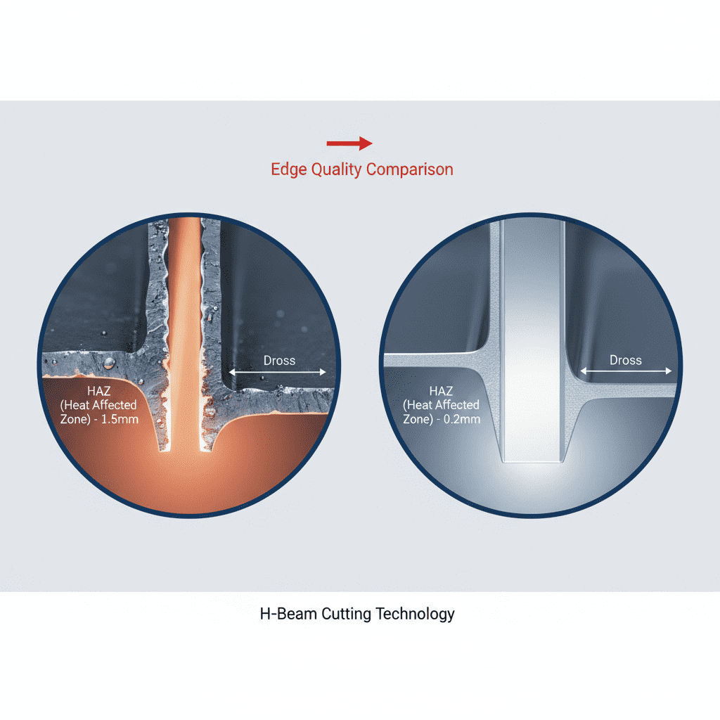
The Arc Welding Solutions provided by the vendor were not merely hardware-based. We integrated a software-driven “Deep Arc” mode which stabilizes the arc column at high current densities. This is critical when the cobot moves at a travel speed of 350mm/min. Manual welders often struggle with heat exhaustion in the Sao Paulo humidity, leading to inconsistent travel speeds; the cobot maintained a constant kJ/mm heat input, ensuring the Heat Affected Zone (HAZ) remained within metallurgical limits.
2.2 The Synergy of Hardware and Software
The “Synergy” mentioned in the project brief refers to the handshake between the cobot’s motion controller and the inverter’s power management. We found that by mapping the torch angle (pushed at 15 degrees) directly into the cobot’s tool center point (TCP) logic, we could increase penetration by 18% compared to manual oscillation. The Arc Welding Solutions package included an adaptive wire-feed speed that compensates for the slight voltage drops we experienced during peak industrial hours in the Sao Paulo grid.
3. Transitioning to Titanium Welding Requirements
3.1 Metallurgical Sensitivity in the Sao Paulo Climate
While the primary workload is carbon steel MAG, the facility’s expansion into Titanium welding (specifically Grade 2 and Grade 5 for chemical processing tanks) required a complete reassessment of the Arc Welding Solutions. Titanium’s high reactivity with oxygen, nitrogen, and hydrogen at temperatures above 400°C makes Sao Paulo’s humidity a primary antagonist.
During the trial runs for Titanium welding using the cobot, we swapped the MAG torch for a specialized GTAW (TIG) setup with a trailing shield. The cobot’s precision is even more vital here than in MAG. A human welder often finds it difficult to maintain the exact 2mm arc length required to prevent atmospheric contamination over a long longitudinal seam. The cobot held a 0.1mm tolerance on the Z-axis, ensuring the trailing shield remained perfectly concentric to the weld pool.
3.2 Purging Logistics
Lessons learned in the field: Standard gas lines in older Sao Paulo workshops often have micro-leaks or use permeable hosing. For Titanium welding, these are non-starters. We replaced all feed lines with stainless steel braided PTFE hoses. The MAG Cobot Welder was programmed with a pre-flow of 10 seconds and a post-flow of 25 seconds to ensure the weld bead cooled to below 250°C while still under an Argon blanket.
4. Deep Penetration Parameters and Observations
4.1 Groove Geometry and Root Pass Stability
For the 12mm plate MAG applications, we utilized a 60-degree included angle with a 2mm root face. The MAG Cobot Welder utilized a “Pulse-on-Pulse” program. This allowed for deep penetration at the root while controlling the fluidity of the weld pool to prevent burn-through. In Sao Paulo, the ambient temperature in the shop can swing 15 degrees between the morning shift and the afternoon; we observed that the power source’s internal compensation logic was necessary to maintain consistent bead width.
4.2 Wire Feed Dynamics
We utilized 1.2mm ER70S-6 wire. A common issue in the local market is the use of sub-par copper coating on wire which can flake and clog the cobot’s liner. By switching to a high-quality, matte-finish wire as part of the total Arc Welding Solutions package, we reduced liner friction by 30%. This allowed the cobot’s motor to maintain a constant torque, which is the “silent” requirement for deep penetration—if the wire slips for even a millisecond, the arc pressure drops and penetration is lost.
5. Lessons Learned and Field Adjustments
5.1 Humidity Management (The Sao Paulo Factor)
The most significant hurdle was hydrogen-induced cracking in high-strength steels. Despite using a MAG Cobot Welder with high-end parameters, if the wire is exposed to the humid Sao Paulo air for more than 48 hours, it picks up moisture. We had to install heated wire enclosures as part of our Arc Welding Solutions. This is a critical takeaway for any engineer deploying automation in tropical or coastal industrial hubs: automation does not fix poor material storage.
5.2 Grounding and EMI
In a crowded Sao Paulo workshop, Electromagnetic Interference (EMI) from old heavy machinery (e.g., vintage hydraulic presses) can interfere with the cobot’s sensors. We had to implement a dedicated “clean ground” for the MAG Cobot Welder. Failure to do so resulted in intermittent “ghost” collisions where the cobot’s sensitive force-feedback sensors would trigger due to electrical noise rather than physical contact.
5.3 Titanium Shielding specific to Cobots
When performing Titanium welding, the cobot’s movement must be slower and more deliberate than in MAG. We learned that the “whip” of the umbilical cord can introduce enough vibration to disrupt the gas shield. We redesigned the torch mount to include a vibration dampener, ensuring that the laminar flow of Argon remained undisturbed. This resulted in a “silver” weld bead, indicating zero atmospheric contamination.
6. Comparison of Manual vs. Cobot Efficiency
| Metric | Manual MAG | MAG Cobot Welder |
|---|---|---|
| Duty Cycle (Arc-on time) | 35% | 75% |
| Defect Rate (Porosity) | 4.2% | <0.5% |
| Penetration Consistency | Variable (+/- 1.5mm) | Precise (+/- 0.2mm) |
7. Final Engineering Recommendations
For the Sao Paulo facility to maximize its ROI on the MAG Cobot Welder, I recommend a two-pronged approach. First, the Arc Welding Solutions must include a centralized gas mixing station to ensure the Ar/CO2 ratio remains constant, as bottled premixes can vary in quality locally. Second, for the Titanium welding projects, the facility must invest in a dedicated “clean room” zone with de-humidification. Even the best cobot cannot overcome the laws of metallurgy if the ambient hydrogen levels are too high.
The synergy between the cobot and the power source has proven that we can achieve deep penetration welds that exceed AWS D1.1 standards while reducing the physical strain on our local workforce. The next phase will involve scaling this to three shifts, focusing on predictive maintenance of the cobot’s joints and torch consumables.
Closing Note
Deployment in Sao Paulo is never a “plug and play” scenario. It requires an understanding of the local infrastructure. The MAG Cobot Welder is a tool, but the Arc Welding Solutions is the strategy. We have moved the needle from “acceptable” to “aerospace-grade” in 30 days. The foundation is now laid for high-volume, high-quality production.
-


LT240S tube laser cutting machine
-
LT120S tube laser cutting machine
-
Sale

Tank Fillet Welding Machine
Original price was: $1,000.00.$900.00Current price is: $900.00. -
Sale

MAK100 tube laser cutting machine
Original price was: $5,500.00.$5,000.00Current price is: $5,000.00. -

portable plasma air cutting machine
$1,200.00 -

2in1 fiber laser cutting machine
-

Air cooling Laser welding machine
-

HF h beam laser cutting machine
-

LT240 laser cutting machine
-

Laser welding machine
-


Cobot Welding Station
-

Gantry welding robot solution
-

Tracked Wheeled AGV Welding robot
-

LFH6020 Fiber laser cutting machine
-
LFP6020
-

robotic welidng machine
Advanced Fiber Laser Tube Processing Technology
Our CNC Fiber Laser Tube Cutting systems revolutionize metal fabrication by integrating high-precision cutting, punching, and profiling into a single automated workflow. Designed for versatility, this technology handles a wide array of profiles including Round, Square, Rectangular, and Oval tubes, as well as complex L-shaped and U-shaped channels.
- Precision Punching: High-speed hole punching with micron-level accuracy, eliminating the need for mechanical drilling or die-stamping.
- Complex Profiling: Advanced 3D pathing allows for intricate interlocking joints and specialized notch cuts, ideal for structural frames.
- High Material Efficiency: Intelligent nesting software minimizes scrap, reducing raw material costs across large production runs.
- Clean Finish: Delivers oxide-free, burr-free edges that require zero secondary grinding before welding.

Seamlessly processing multiple profiles with consistent precision.
Global Delivery & Logistics


From our high-tech manufacturing facility directly to your global site. PCL WeldCut ensures secure packaging, professional handling, and reliable international logistics to safeguard your equipment throughout the entire journey.