Field Report: Deployment of Deep Penetration Collaborative Arc Welding System
Location: Pinthong Industrial Estate, Chonburi, Thailand
Project Overview and Environmental Parameters
This report details the field integration of a Deep Penetration Collaborative Arc Welding System at a heavy fabrication facility in Chonburi. The objective was the transition of thick-section Carbon Steel welding from purely manual Flux-Cored Arc Welding (FCAW) to a hybrid Automated Welding workflow. The site conditions presented standard tropical challenges: ambient temperatures averaging 34°C with relative humidity peaking at 85%, necessitating rigorous cooling protocols for both the power sources and the collaborative manipulators.
Synergy of Collaborative Arc Welding Systems and Automated Welding
In the context of the Chonburi workshop, the distinction between “Collaborative” and “Automated” is functional rather than semantic. While Automated Welding refers to the execution of the weld path and parameter modulation without real-time human intervention, the Collaborative Arc Welding System acts as the interface that allows our senior welders to bridge the gap between manual expertise and robotic precision.
The synergy observed on-site focused on “lead-through teaching.” Traditional industrial robots require extensive downtime for G-code adjustments when part fit-up varies. In contrast, the collaborative system allows the operator to manually guide the torch to the start point of a carbon steel seam, record the vector, and initiate the automated sequence. This is critical in Chonburi’s supply chain, where upstream plate cutting occasionally results in gap variances that fixed automation cannot handle. The collaborative system permits “on-the-fly” offset adjustments, combining human spatial recognition with the duty cycle of a machine.
Deep Penetration Mechanics in Carbon Steel Welding
The core technical requirement for this deployment was achieving 8mm to 10mm penetration in a single pass on S355JR grade Carbon Steel welding applications without the need for extensive beveling. Traditional Gas Metal Arc Welding (GMAW) often suffers from lack of fusion at these depths unless a wide V-groove is prepared.
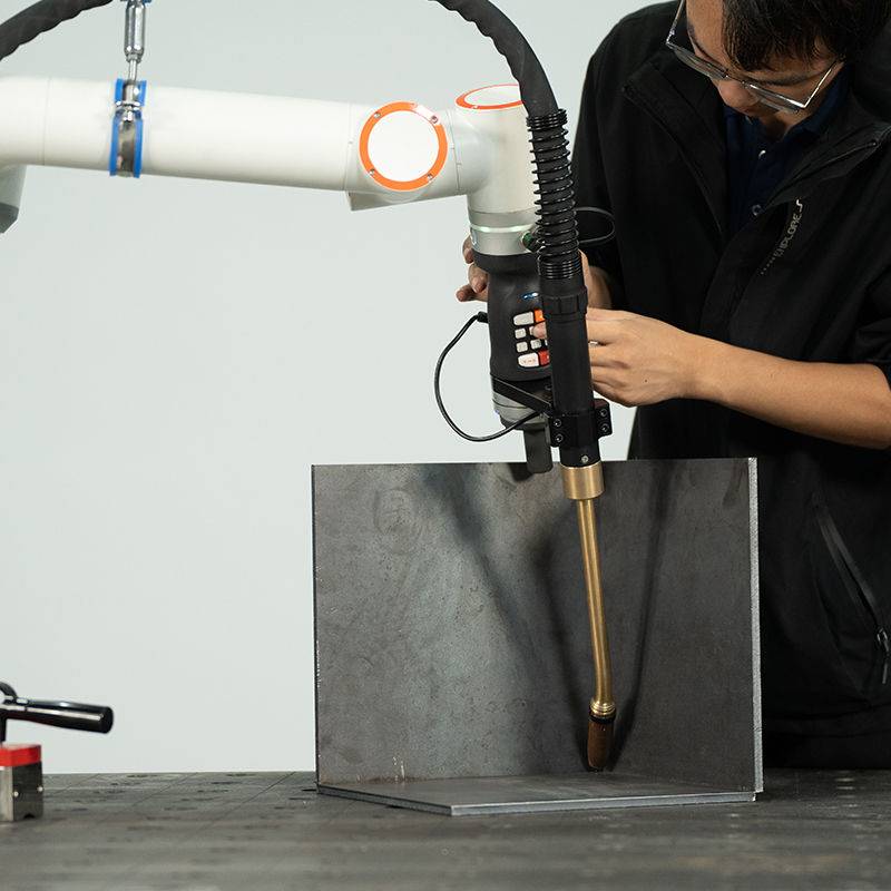
Our collaborative system utilized a high-energy density modified pulse waveform. This specific “Deep Penetration” mode creates a highly concentrated arc column that pushes the plasma force deeper into the molten pool. By automating the travel speed at a consistent 350mm/min, we maintained a stable keyhole effect. This would be physically impossible for a manual welder to sustain over a 2-meter seam due to the intense radiant heat and the precise torch angle required to prevent the weld pool from collapsing.
Technical Integration and Parameter Validation
Wire Feed and Gas Shielding Challenges
Working in Chonburi requires specific attention to the Carbon Steel welding consumables. We utilized ER70S-6 solid wire (1.2mm). A recurring issue in high-humidity environments is moisture contamination in the wire conduit, leading to hydrogen-induced cracking or porosity. To mitigate this, we integrated pressurized wire delivery packs and heated gas regulators for the 80/20 Ar-CO2 mix.
The Automated Welding sequence was programmed with a specific pre-flow and post-flow logic to compensate for the workshop’s ambient cross-drafts. Even within a sheltered facility, Chonburi’s coastal winds can disrupt shielding gas envelopes. The collaborative system’s integrated sensors allowed us to set “Interruption Triggers”—if the gas flow dropped below 15 L/min due to a regulator freeze or line kink, the arc would extinguish immediately, saving the workpiece from rework.
Thermal Management and Duty Cycle
The Collaborative Arc Welding System was pushed to a 70% duty cycle. In the Chonburi heat, the primary bottleneck was not the collaborative arm’s motors, but the torch’s liquid cooling unit. We observed that the deep penetration mode generates significantly higher back-radiation from the carbon steel base plate. We had to upgrade the coolant to a high-conductivity glycol mix and increase the reservoir capacity to ensure the Automated Welding cycle didn’t trigger thermal alarms during long-seam longitudinal welds.
Practical Application: The V-Groove Replacement
One of the significant “Lessons Learned” during this field deployment was the reduction in prep time. For 12mm Carbon Steel welding, the previous SOP required a 60-degree V-prep. By leveraging the Deep Penetration Collaborative Arc Welding System, we moved to a square-butt configuration with a 1mm gap.
The Automated Welding parameters were tuned as follows:
- Current: 340A – 360A (Pulse)
- Voltage: 32V – 34V
- Travel Speed: Constant 32 cm/min
- Torch Angle: 5-degree push
The result was a 40% reduction in filler metal consumption and a 60% reduction in grinding time. The “Collaborative” aspect was vital here: the operator monitored the arc through a darkened camera feed on the tablet interface, adjusting the voltage trim in real-time as the heat built up in the plate, preventing burn-through at the end of the run.
Lessons Learned and Field Troubleshooting
1. Sensor Drift in High Humidity
In Chonburi’s environment, the capacitive touch sensors on the collaborative arm experienced occasional “ghosting.” Moisture buildup on the teach pendant or the arm joints can be interpreted by the controller as a human collision, triggering an emergency stop. Lesson: We implemented a daily “dry-wipe” protocol and installed silica-gel desiccant packs inside the controller cabinet. Automated welding systems in the tropics must be rated to at least IP54.
2. Grounding and HF Interference
High-frequency arc starts used in some Collaborative Arc Welding Systems can interfere with the collaborative arm’s encoders. We found that the carbon steel worktables in the Chonburi plant were poorly grounded. This led to “encoder jitter” where the arm would vibrate during the weld. Lesson: Dedicated copper busbar grounding for the workpiece and the robot base is mandatory. Never rely on the building’s structural steel for the return path.
3. Operator Psychology and Transition
The shift to Automated Welding often meets resistance. However, because this was a Collaborative Arc Welding System, the senior welders felt they were “upgrading” rather than being “replaced.” They still own the weld; they just use a robotic “third arm” to hold the torch. In the 38°C heat of a Chonburi afternoon, the reduction in physical fatigue was the primary driver for operator adoption.
Metallurgical Results for Carbon Steel
Cross-sectional macro-etch tests were performed on-site. The deep penetration waveform produced a narrow Heat Affected Zone (HAZ) compared to manual FCAW. This is a critical advantage for the structural integrity of the Carbon Steel welding projects handled at this facility. The grain structure within the fusion zone showed a refined dendritic pattern, indicative of the stable cooling rates achieved by the consistent travel speed of the automated system.
Charpy V-Notch (CVN) testing at -20°C showed an average toughness of 45J, well above the 27J requirement. This confirms that the high-current density of the Automated Welding process did not negatively impact the fracture toughness of the carbon steel substrate, provided the interpass temperature was kept below 250°C (monitored via infrared sensors integrated into the collaborative cell).
Final Recommendations for Regional Scaling
For further deployment of Collaborative Arc Welding Systems across other Thailand-based facilities, the following should be standardized:
Hardware Specification
Standardize on water-cooled torches regardless of amperage. The ambient heat in Southeast Asian workshops leaves no margin for air-cooled systems during high-penetration cycles.
Software and Training
Develop “Weld Libraries” specific to Carbon Steel welding thicknesses common in the region (6mm, 8mm, 12mm). This allows operators to load a baseline Automated Welding program and only use the collaborative “hand-guide” feature for fine-tuning the path.
Environmental Hardening
All controller units must be housed in air-conditioned or heat-exchanged cabinets to prevent PCB failure due to the combination of conductive dust (from grinding) and high humidity.
The Chonburi deployment demonstrates that when Automated Welding is approached through a collaborative framework, the technical barriers to high-quality deep penetration welds on carbon steel are significantly lowered, while productivity and weld consistency are doubled compared to manual benchmarks.
-


Cantilever Welding Robot solution
-


GF laser cutting machine
-

P3015 plasma cutting machine
-

LFP3015 Fiber Laser Cutter
-

pipe plasma cutting machine
-
LFH 4020 Fiber Laser Cutting Machine
-
LFP4020
-

gantry plasma air cutting machine
-

3D robot cutting machine
-

8 axis plasma cutting machine
-

5 axis plasma cutting machine
-

LT360 tube laser cutting machine
-

robot welding workstation
-

SF6060 fiber laser cutting machine
Advanced Fiber Laser Tube Processing Technology
Our CNC Fiber Laser Tube Cutting systems revolutionize metal fabrication by integrating high-precision cutting, punching, and profiling into a single automated workflow. Designed for versatility, this technology handles a wide array of profiles including Round, Square, Rectangular, and Oval tubes, as well as complex L-shaped and U-shaped channels.
- Precision Punching: High-speed hole punching with micron-level accuracy, eliminating the need for mechanical drilling or die-stamping.
- Complex Profiling: Advanced 3D pathing allows for intricate interlocking joints and specialized notch cuts, ideal for structural frames.
- High Material Efficiency: Intelligent nesting software minimizes scrap, reducing raw material costs across large production runs.
- Clean Finish: Delivers oxide-free, burr-free edges that require zero secondary grinding before welding.

Seamlessly processing multiple profiles with consistent precision.
Global Delivery & Logistics



From our high-tech manufacturing facility directly to your global site. PCL WeldCut ensures secure packaging, professional handling, and reliable international logistics to safeguard your equipment throughout the entire journey.