Field Engineering Report: Robotic Integration and Thermal Management in Eindhoven
This report details the technical deployment and optimization of an air-cooled MIG/MAG Welding Robot system at a Tier-1 industrial manufacturing facility in Eindhoven, Netherlands. The project focused on high-volume production of structural components, specifically addressing the complexities of Carbon Steel welding using advanced Arc Welding Solutions. As the lead engineer on-site, my objective was to stabilize the process window while maintaining a rigorous production schedule characteristic of the Brainport region’s high-tech manufacturing standards.
1. Project Scope and Environmental Context
The Eindhoven facility operates under a high-mix, medium-volume strategy. The primary challenge was replacing legacy manual stations with a fully integrated MIG/MAG Welding Robot. Unlike liquid-cooled systems, the client opted for an air-cooled torch configuration to minimize maintenance overhead and potential coolant leak contamination on the shop floor. In the context of Carbon Steel welding, where heat input must be carefully managed to maintain mechanical properties, the choice of air-cooled hardware required a precise calibration of the Arc Welding Solutions software parameters.
2. Technical Specifications of the MIG/MAG Welding Robot
The system comprises a 6-axis articulated arm with a payload capacity optimized for a high-performance air-cooled torch. Integration with the power source was achieved via a high-speed Fieldbus interface, ensuring sub-millisecond communication between the robot controller and the welding inverter.
Hardware Configuration:
- Torch Geometry: 45-degree neck for optimal accessibility in tight joint geometries.
- Wire Feeding: A synchronized dual-drive system located at the robot’s shoulder to prevent wire slipping during high-speed air-moves.
- Cooling Logic: Forced-air cooling cycles integrated into the robot’s “between-part” routines to mitigate nozzle overheating.
The synergy between the MIG/MAG Welding Robot and the peripheral Arc Welding Solutions (such as the automatic nozzle cleaner and the wire-cut station) is what defines the system’s uptime. In Eindhoven, we found that even a 2-millimeter deviation in the Tool Center Point (TCP) due to thermal expansion of the air-cooled neck could lead to lack-of-fusion defects in Carbon Steel welding applications.
3. Implementing Advanced Arc Welding Solutions
The term “Arc Welding Solutions” refers to the holistic ecosystem of software and power-source characteristics. For this Eindhoven project, we utilized a “Pulse-on-Pulse” methodology. This was critical for Carbon Steel welding on 6mm plates where gap bridging was inconsistent due to upstream laser-cutting tolerances.
Waveform Optimization:
We implemented a modified spray transfer mode. By fine-tuning the peak current and background current, the MIG/MAG Welding Robot achieved a stable arc that minimized spatter. Spatter reduction is not just an aesthetic requirement; in a robotic cell, reduced spatter means the gas nozzle remains clear for longer periods, extending the life of the air-cooled consumables. This is a prime example of how Arc Welding Solutions directly influence the mechanical reliability of the MIG/MAG Welding Robot hardware.
4. Challenges in Carbon Steel Welding
Carbon Steel welding in an industrial setting like Eindhoven requires strict adherence to ISO 5817 standards. Our primary metallurgical concern was the Heat Affected Zone (HAZ). Because the MIG/MAG Welding Robot can travel at significantly higher speeds than a human welder, there is a temptation to “run hot and fast.” However, this can lead to centerline cracking if the cooling rate is too aggressive.
Specific Parameter Adjustments:
- Gas Composition: We moved from a standard 100% CO2 (MAG) to an 82% Argon / 18% CO2 mix. This transition, part of our broader Arc Welding Solutions strategy, provided a more stable arc for the robot and reduced the thermal load on the air-cooled torch.
- Wire Selection: An ER70S-6 wire was selected for its high silicon and manganese content, which helps in deoxidizing the weld pool—crucial for the slightly scaled surfaces of the carbon steel plates provided.
5. Thermal Management of the Air-Cooled System
One of the most significant “lessons learned” during the Eindhoven commission was the limitation of the air-cooled MIG/MAG Welding Robot during continuous Carbon Steel welding of long seams. After 4 minutes of continuous arc-on time at 280 Amps, the contact tip temperature reached a critical threshold, leading to increased electrical resistance and “micro-arcing” inside the tip.
The Engineering Solution:
Instead of switching to water-cooling—which would have required a complete teardown—we optimized the Arc Welding Solutions by programming “air-blast” pauses. The MIG/MAG Welding Robot was programmed to move to a specific cooling station every three parts. Here, high-pressure compressed air was blown through the torch shroud. This dropped the tip temperature by 40 degrees Celsius in a 15-second window, allowing us to maintain a 70% duty cycle without consumable failure.
6. Integration Synergy: Robot and Software
The success in Eindhoven was predicated on the seamless communication between the MIG/MAG Welding Robot and the Arc Welding Solutions. We utilized a “Touch Sensing” routine where the robot uses the welding wire itself to locate the part position before striking the arc.
For Carbon Steel welding, part fit-up is rarely perfect. By using the robot’s high-speed sensing capabilities, we could adjust the weld path in real-time. This ensures that the Arc Welding Solutions—specifically the adaptive fill parameters—are applied exactly where the joint volume requires them. This synergy reduces scrap rates by approximately 12% compared to non-adaptive robotic systems.
7. Lessons Learned and Field Observations
Working in the Eindhoven industrial sector provided several key takeaways for future MIG/MAG Welding Robot deployments:
The “Air-Cooled” Fallacy:
Many engineers assume air-cooled means “low power.” We proved that with the right Arc Welding Solutions, specifically pulsed-arc waveforms that reduce the overall heat input, you can perform heavy-duty Carbon Steel welding without the complexity of water chillers. However, you must monitor the TCP. We implemented a daily TCP check routine where the robot touches a fixed spike to calibrate for any heat-induced neck warp.
Shielding Gas Turbulence:
In the Eindhoven workshop, the overhead ventilation was particularly strong. This created turbulence at the gas shroud of the MIG/MAG Welding Robot. We had to increase the gas flow from 15 L/min to 22 L/min and switch to a tapered nozzle to maintain laminar flow. This is a critical adjustment when performing Carbon Steel welding to prevent porosity that is often invisible to the naked eye but fails X-ray inspection.
Wire Feed Path:
Because the MIG/MAG Welding Robot moves through complex orientations, the conduit liner for the wire must be high-quality Teflon or specialized steel. We noticed “hunting” in the arc (voltage fluctuations) when the robot’s 5th axis was at extreme angles. Replacing the standard liner with a low-friction variant solved the wire-feed consistency issues, proving that the physical delivery system is as vital as the digital Arc Welding Solutions.
8. Final Conclusion on Eindhoven Site Operations
The deployment of the air-cooled MIG/MAG Welding Robot in Eindhoven has been a benchmark for efficiency in Carbon Steel welding. By prioritizing the integration of smart Arc Welding Solutions over raw cooling power, we achieved a system that is both robust and easy to maintain. The key to success was not just the hardware, but the meticulous calibration of the arc characteristics to match the thermal limits of the air-cooled torch and the metallurgical requirements of the carbon steel.
Future installations should continue to focus on adaptive sensing and waveform manipulation to further bridge the gap between air-cooled simplicity and high-amperage performance. The Eindhoven facility now operates at a 30% higher throughput than its previous manual configuration, with a defect rate of less than 0.5%.
Report Filed By:
Senior Welding Engineer, Field Operations
Location: Eindhoven, NL
-


LT240S tube laser cutting machine
-
LT120S tube laser cutting machine
-
Sale

Tank Fillet Welding Machine
Original price was: $1,000.00.$900.00Current price is: $900.00. -
Sale

MAK100 tube laser cutting machine
Original price was: $5,500.00.$5,000.00Current price is: $5,000.00. -

portable plasma air cutting machine
$1,200.00 -

2in1 fiber laser cutting machine
-

Air cooling Laser welding machine
-

HF h beam laser cutting machine
-

LT240 laser cutting machine
-

Laser welding machine
-


Cobot Welding Station
-

Gantry welding robot solution
-

Tracked Wheeled AGV Welding robot
-

LFH6020 Fiber laser cutting machine
-
LFP6020
-

robotic welidng machine
Advanced Fiber Laser Tube Processing Technology
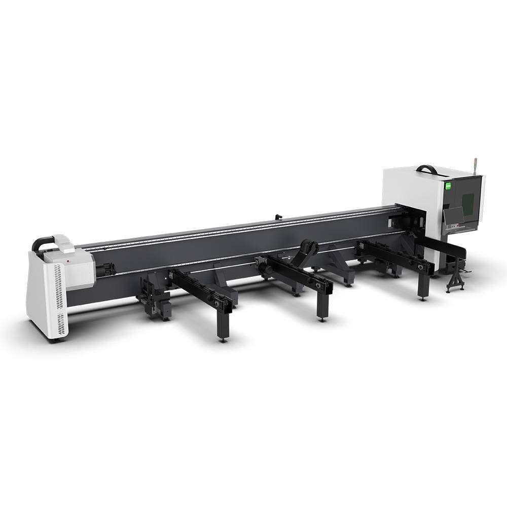
Our CNC Fiber Laser Tube Cutting systems revolutionize metal fabrication by integrating high-precision cutting, punching, and profiling into a single automated workflow. Designed for versatility, this technology handles a wide array of profiles including Round, Square, Rectangular, and Oval tubes, as well as complex L-shaped and U-shaped channels.
- Precision Punching: High-speed hole punching with micron-level accuracy, eliminating the need for mechanical drilling or die-stamping.
- Complex Profiling: Advanced 3D pathing allows for intricate interlocking joints and specialized notch cuts, ideal for structural frames.
- High Material Efficiency: Intelligent nesting software minimizes scrap, reducing raw material costs across large production runs.
- Clean Finish: Delivers oxide-free, burr-free edges that require zero secondary grinding before welding.

Seamlessly processing multiple profiles with consistent precision.
Global Delivery & Logistics



From our high-tech manufacturing facility directly to your global site. PCL WeldCut ensures secure packaging, professional handling, and reliable international logistics to safeguard your equipment throughout the entire journey.