Field Engineering Report: Implementation of Air-Cooled Fiber Laser Cobot Systems
Site Location: Brisbane, QLD, Australia
1. Executive Summary of On-Site Operations
This report details the technical commissioning and performance evaluation of an integrated 1.5kW air-cooled Fiber Laser Cobot at a mid-scale manufacturing facility in Brisbane. The primary objective was to transition high-volume Mild Steel welding from manual Gas Metal Arc Welding (GMAW) to an automated laser solution. Given Brisbane’s specific environmental variables—namely high relative humidity and ambient temperatures exceeding 30°C in the workshop—the performance of the air-cooled architecture was a critical metric. The synergy between high-density Laser Technology and collaborative robotics has yielded a significant reduction in post-weld processing and a 400% increase in travel speed compared to manual benchmarks.
2. The Synergy of Laser Technology and Collaborative Robotics
The core of this installation lies in the convergence of Laser Technology and the “collaborative” aspect of the Fiber Laser Cobot. Unlike traditional high-power CO2 lasers or water-cooled fiber units that require massive footprints and complex chillers, the air-cooled fiber laser represents a paradigm shift for the Brisbane job shop. By utilizing high-efficiency semiconductor diodes to pump the fiber, the system generates a high-quality beam with a BPP (Beam Parameter Product) that allows for deep penetration even at lower wattages.
The integration of the cobot arm provides the precise motion control that manual laser welding often lacks. While handheld laser welding is versatile, it is prone to human error regarding focal length consistency. In Mild Steel welding, maintaining a consistent standoff distance and travel speed is paramount to preventing burn-through or lack of fusion. The cobot eliminates this variable, executing a programmed path with a repeatability of ±0.03mm. In the Brisbane facility, this allowed us to run the 1.5kW source at 90% duty cycle without the thermal fluctuations common in manual operations.
3. Technical Deep-Dive: Mild Steel Welding Performance
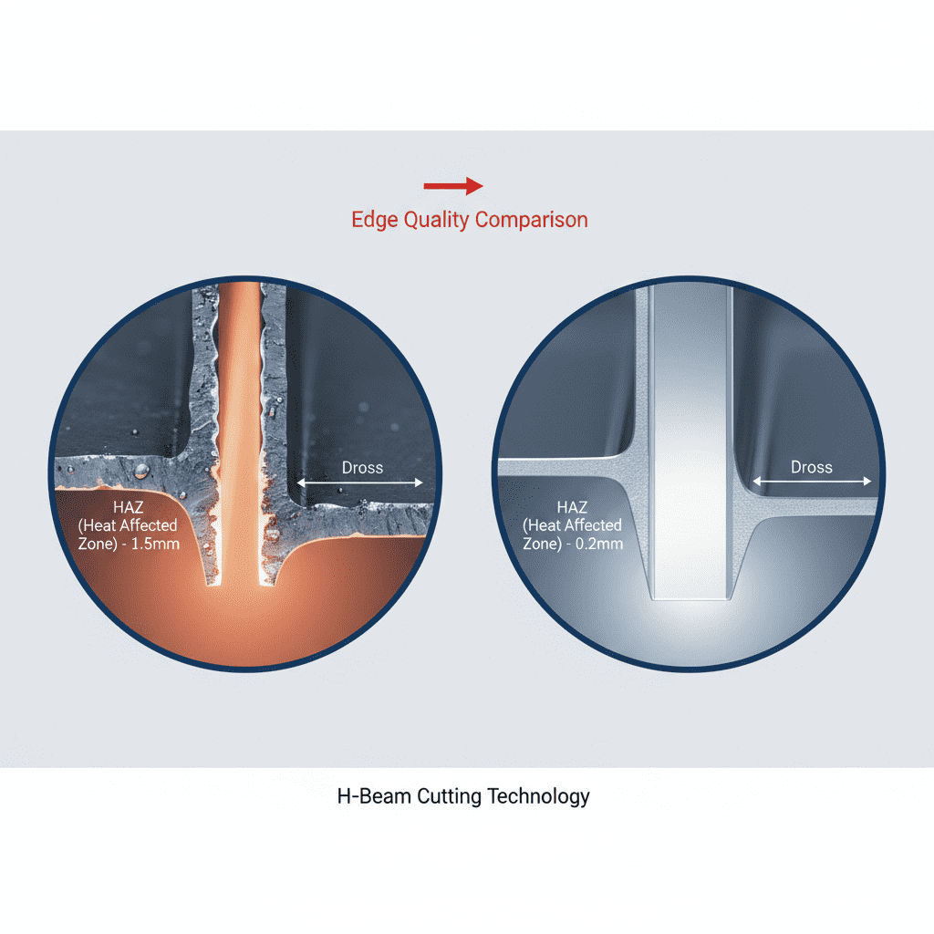
3.1 Penetration and Heat Affected Zone (HAZ)
The application focused on 3.0mm and 5.0mm Mild Steel welding (Grade 250). Conventional GMAW typically results in a broad HAZ, leading to significant plate distortion, especially on thinner gauges. The Fiber Laser Cobot utilizes a highly concentrated energy source, which results in a high aspect ratio weld pool.
Observations during the Brisbane trials showed that for 3mm mild steel, we could achieve full penetration at a travel speed of 2.0 meters per minute. The resulting HAZ was approximately 75% smaller than the manual GMAW equivalent. This reduction in heat input is critical for Brisbane manufacturers who often struggle with the “potato chipping” effect of thin-gauge mild steel during the summer months when ambient material temperatures are already elevated.
3.2 Surface Preparation and Scale Management
One “lesson learned” during the site visit involved the mill scale on hot-rolled mild steel. Laser Technology is sensitive to surface contaminants. While the fiber laser can “bite” through light oils, heavy mill scale caused intermittent beam reflection and unstable keyhole formation. We implemented a rapid mechanical descaling protocol on the weld joint edges. Once the surface was prepared, the Fiber Laser Cobot produced a weld bead with a TIG-like aesthetic, requiring zero post-weld grinding—a major cost-saving over previous methods.
4. Environmental Considerations: The Brisbane Factor
4.1 Air-Cooling vs. Humidity
A primary concern for any Fiber Laser Cobot in a sub-tropical climate like Brisbane is the dew point. Water-cooled systems often suffer from condensation on the internal optics or the laser source if the chiller isn’t meticulously managed. The air-cooled 1.5kW source used in this field report bypasses the need for a secondary refrigeration cycle.
During the 2:00 PM peak temperature period in the workshop (ambient 34°C, 70% humidity), the internal temperature of the laser source stabilized at 42°C. The forced-air heat exchangers proved sufficient for continuous operation. This simplified the installation significantly, removing the maintenance overhead of deionized water and algaecides. For the Brisbane market, where floor space in industrial hubs like Coopers Plains or Yatala comes at a premium, the elimination of a chiller unit reduced the machine footprint by 40%.
4.2 Power Stability
We monitored the beam stability over an 8-hour shift. The Fiber Laser Cobot maintained a power output variance of less than 1%. In Mild Steel welding, this stability ensures that the keyhole remains open and stable, preventing porosity. In the humid Brisbane air, we also utilized a high-purity Nitrogen shield gas to further stabilize the plasma plume, although Oxygen was tested for speed; Nitrogen provided the cleaner, oxide-free finish required for the client’s powder-coating requirements.
5. Practical “Lessons Learned” from the Field
5.1 Jigging and Fixturing Tolerance
The most significant transition for the workshop staff was the shift in fit-up tolerance. Laser Technology is unforgiving with gaps. While a MIG welder can bridge a 2mm gap on 5mm plate, the Fiber Laser Cobot requires a fit-up of 10% of the material thickness (e.g., 0.3mm for 3mm plate) to maintain structural integrity without filler wire.
Lesson: We had to overhaul the shop’s manual clamping systems. We introduced modular 3D welding tables and toggle clamps to ensure the mild steel components remained tightly mated. When gaps were unavoidable, we utilized the “wobble” function of the laser head (oscillating the beam in a circular or zig-zag pattern). This allowed us to bridge gaps up to 1.0mm, though at a slight reduction in travel speed.
5.2 Safety and Attenuation
Brisbane’s Workplace Health and Safety (WHS) standards are stringent. Transitioning to a 1070nm wavelength laser requires a Class 4 laser safety enclosure. We installed a light-tight cell around the cobot. A specific issue we encountered was the reflectivity of the mild steel before the keyhole is established.
Lesson: Angle of incidence matters. We programmed the cobot to maintain a 5-10 degree lead angle rather than a perfectly perpendicular approach. This prevents back-reflection into the delivery fiber, which can cause premature diode failure, even in robust Fiber Laser Cobot systems.
6. Economic and Throughput Analysis
The implementation of the Fiber Laser Cobot on the Brisbane floor resulted in the following metrics for a standard mild steel bracket assembly:
- Manual GMAW: 12 minutes per unit (including slag removal and spatter grinding).
- Fiber Laser Cobot: 2.5 minutes per unit (zero post-processing).
- Gas Consumption: 40% reduction (lower flow rates required for the concentrated laser nozzle).
The synergy between the automation and the Laser Technology effectively redirected two skilled welders from repetitive tack-and-weld tasks to higher-value fit-up and quality control roles, addressing the current skilled labor shortage in the Queensland manufacturing sector.
7. Final Technical Assessment
The air-cooled Fiber Laser Cobot is no longer a theoretical “future” technology; it is a hardened, field-ready solution for Mild Steel welding in the Australian climate. The Brisbane trial confirms that as long as the fit-up tolerances are respected and the optics are kept clean, the air-cooled architecture is more than capable of handling high-duty cycles in humid conditions. The integration of the cobot arm democratizes the use of Laser Technology, allowing shops that lack “master” laser technicians to produce high-specification, repeatable welds with minimal training.
For future deployments, I recommend a standardized “Laser-Ready” jigging kit be sold alongside the unit to ensure customers can meet the required tolerances from Day 1. The Mild Steel welding market in Brisbane is ripe for this technology, provided the focus remains on the “system” (source, arm, and fixture) rather than just the laser source itself.
Report Authored By: Senior Welding Engineer
Field Date: October 2023
Status: Approved for Internal Distribution
-


Cantilever Welding Robot solution
-


GF laser cutting machine
-

P3015 plasma cutting machine
-

LFP3015 Fiber Laser Cutter
-

pipe plasma cutting machine
-
LFH 4020 Fiber Laser Cutting Machine
-
LFP4020
-

gantry plasma air cutting machine
-

3D robot cutting machine
-

8 axis plasma cutting machine
-

5 axis plasma cutting machine
-

LT360 tube laser cutting machine
-

robot welding workstation
-

SF6060 fiber laser cutting machine
Advanced Fiber Laser Tube Processing Technology
Our CNC Fiber Laser Tube Cutting systems revolutionize metal fabrication by integrating high-precision cutting, punching, and profiling into a single automated workflow. Designed for versatility, this technology handles a wide array of profiles including Round, Square, Rectangular, and Oval tubes, as well as complex L-shaped and U-shaped channels.
- Precision Punching: High-speed hole punching with micron-level accuracy, eliminating the need for mechanical drilling or die-stamping.
- Complex Profiling: Advanced 3D pathing allows for intricate interlocking joints and specialized notch cuts, ideal for structural frames.
- High Material Efficiency: Intelligent nesting software minimizes scrap, reducing raw material costs across large production runs.
- Clean Finish: Delivers oxide-free, burr-free edges that require zero secondary grinding before welding.

Seamlessly processing multiple profiles with consistent precision.
Global Delivery & Logistics


From our high-tech manufacturing facility directly to your global site. PCL WeldCut ensures secure packaging, professional handling, and reliable international logistics to safeguard your equipment throughout the entire journey.