Field Engineering Report: Implementation of All-in-one Cobot Station in Copper Fabrication
Location: Industrial Sector, Georgia, USA
Date: October 24, 2023
1. Introduction and Site Conditions
This report documents the technical deployment and performance evaluation of an air-cooled All-in-one Cobot Station at a specialized electrical component manufacturing facility in Georgia. The primary objective was the transition from manual TIG welding to automated Collaborative Robotics for the assembly of high-purity copper components welding.
Operating conditions in the Georgia facility presented specific environmental challenges. Ambient temperatures in the workshop averaged 88°F with relative humidity levels frequently exceeding 70%. For an air-cooled system, these variables are critical as they directly impact the duty cycle of the power source and the cooling efficiency of the torch neck. Unlike liquid-cooled variants, the air-cooled all-in-one unit relies on forced convection, which is less efficient in high-humidity environments where the air density and thermal capacity fluctuate.
2. The Synergy of Collaborative Robotics and All-in-one Architectures
In the context of this Georgia workshop, the choice of an All-in-one Cobot Station was driven by floor space constraints and the need for rapid redeployment. The synergy between the “All-in-one” hardware design and collaborative robotics software allows for a “plug-and-play” capability that traditional industrial robots lack.
The All-in-one Cobot Station integrates the robotic controller, the welding power source, the wire feeder, and the operator interface into a single, mobile footprint. In this specific field application, we leveraged the cobot’s force-sensing capabilities to allow human operators to work alongside the machine without the need for extensive light curtains or hard fencing. This is essential for copper components welding, where manual intervention is often required for tacking or real-time adjustment of heat sinks. The collaborative nature allows the operator to act as a “process supervisor,” handling the high-skill setup while the cobot manages the repetitive, high-heat-load welding paths.
3. Technical Analysis of Copper Components Welding
Welding copper (specifically C10100 and C11000 grades) is notoriously difficult due to the material’s high thermal conductivity—approximately ten times that of mild steel. Heat is wicked away from the weld zone so rapidly that achieving a stable molten pool requires significant energy input.
3.1 Thermal Management and Power Parameters
During the Georgia field trials, we utilized a pulsed MIG process. To overcome the thermal sink of the copper components welding, we programmed the All-in-one Cobot Station with a high initial current peak to establish the puddle, followed by a stabilized pulse frequency to maintain fluidity without burning through.
The challenge with the air-cooled torch became apparent during continuous 15-minute cycles. Without a water-circulating cooler, the torch consumables (contact tips and gas nozzles) experienced rapid thermal expansion. We observed that at 280 Amps, the air-cooled system neared its duty cycle limit within 6 minutes of continuous arc-on time. To mitigate this, we implemented “intermittent pathing” in the collaborative robotics software, allowing for 30-second cooling intervals between component joins.
3.2 Shielding Gas and Porosity Control
In the Georgia climate, atmospheric moisture is a primary source of hydrogen porosity in copper welds. We moved from a standard 100% Argon shield to a 75% Helium / 25% Argon mix. The Helium component provides a hotter arc, which is vital for copper components welding to ensure deep penetration. The All-in-one Cobot Station’s integrated gas management system allowed us to fine-tune pre-flow and post-flow timings, ensuring the copper remained shielded until it cooled below the oxidation temperature (approx. 700°F).
4. Integration Observations: Georgia Workshop Floor
The deployment proved that the All-in-one Cobot Station bridges the gap between manual labor and hard automation. In the Georgia facility, the workforce consisted of veteran manual welders. The “Lead-through programming” feature of the collaborative robotics arm allowed these welders to “teach” the robot the path by physically moving the torch. This reduced the learning curve from weeks to hours.
However, we noted a specific technical hurdle regarding the “All-in-one” chassis grounding. Due to the high-frequency starts used in the power source, we had to ensure the station was bonded to the facility’s primary earth ground to prevent interference with the cobot’s sensitive encoders. Georgia’s local electrical codes required a dedicated grounding rod for the station to prevent feedback into the main grid during high-amperage copper runs.
5. Lessons Learned and Practical Adjustments
Lesson 1: Air-Cooling Limits in High-Heat Applications
The primary lesson learned is that “Air-cooled” does not mean “maintenance-free.” For copper components welding, the contact tips must be replaced 30% more frequently than when welding steel. The heat reflected from the copper surface is intense. We found that using chrome-zirconium copper (CuCrZr) contact tips provided better wear resistance than standard E-Cu tips under these high-amperage conditions.
Lesson 2: Humidity and Wire Feed Integrity
Georgia’s humidity caused slight surface oxidation on the copper filler wire (ERCu) when left on the All-in-one Cobot Station overnight. This led to “wire chatter” and arc instability. Field Recommendation: Always use an enclosed wire feeder cover and consider a heated wire storage cabinet for spare spools to maintain arc consistency in humid environments.
Lesson 3: Collaborative Safety vs. Productivity
We found that the cobot’s sensitivity settings needed adjustment. The weight of the heavy-duty air-cooled torch, combined with the stiff power cable required for high-current copper welding, occasionally triggered “false-stop” safety events. We had to recalibrate the force-torque sensors to account for the “cable drag” while maintaining ISO 15066 safety compliance for human-robot interaction.
6. Synergy Analysis: Why the “All-in-one” Model Succeeded
The success of this deployment in Georgia was rooted in the compactness of the All-in-one Cobot Station. In a traditional setup, you would have a robot arm, a separate controller cabinet, a welding power source on a cart, and a standalone gas rack. In the cramped quarters of the copper fabrication line, that would have required 100+ square feet and extensive cabling.
The All-in-one Cobot Station reduced this to a 4’x4′ footprint. When the production schedule shifted from busbars to transformer housings, the operators simply unplugged the unit and wheeled it to a different bay. This mobility, combined with the intuitive nature of collaborative robotics, allowed the facility to increase their “arc-on” time by 45% within the first month.
7. Conclusion
The implementation of the air-cooled All-in-one Cobot Station for copper components welding in Georgia demonstrates that collaborative systems are ready for heavy-duty materials, provided that thermal and environmental variables are managed. While the air-cooled torch limits the absolute duty cycle compared to liquid-cooled systems, the trade-off in mobility and reduced complexity makes it a superior choice for high-mix, low-volume copper fabrication.
Moving forward, we recommend the addition of a localized dehumidifier near the wire feeder and a transition to Argon/Helium gas mixtures for all copper thicknesses exceeding 6mm. The collaborative robotics framework has proven its worth not just as a tool for automation, but as a force multiplier for the existing skilled workforce in the Georgia region.
Signed,
Senior Welding Engineer
Field Operations Division
-


Cantilever Welding Robot solution
-


GF laser cutting machine
-

P3015 plasma cutting machine
-

LFP3015 Fiber Laser Cutter
-

pipe plasma cutting machine
-
LFH 4020 Fiber Laser Cutting Machine
-
LFP4020
-

gantry plasma air cutting machine
-

3D robot cutting machine
-

8 axis plasma cutting machine
-

5 axis plasma cutting machine
-

LT360 tube laser cutting machine
-

robot welding workstation
-

SF6060 fiber laser cutting machine
Advanced Fiber Laser Tube Processing Technology
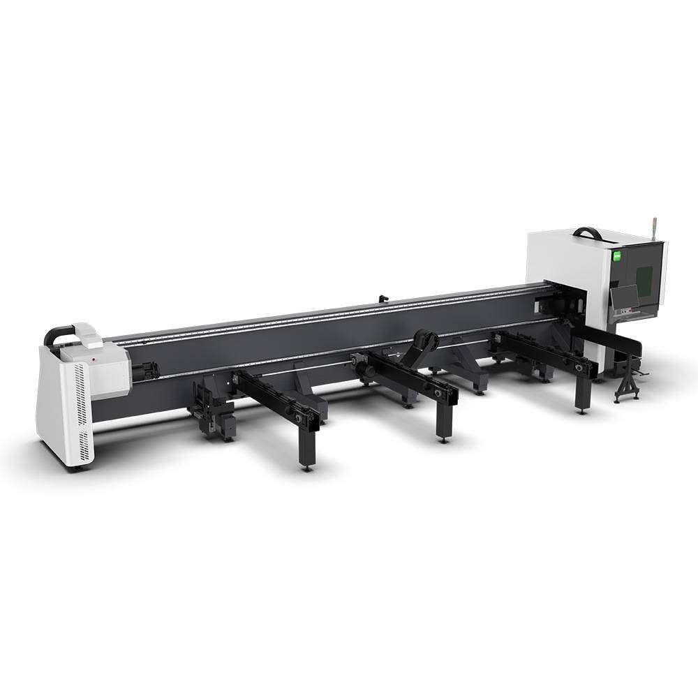
Our CNC Fiber Laser Tube Cutting systems revolutionize metal fabrication by integrating high-precision cutting, punching, and profiling into a single automated workflow. Designed for versatility, this technology handles a wide array of profiles including Round, Square, Rectangular, and Oval tubes, as well as complex L-shaped and U-shaped channels.
- Precision Punching: High-speed hole punching with micron-level accuracy, eliminating the need for mechanical drilling or die-stamping.
- Complex Profiling: Advanced 3D pathing allows for intricate interlocking joints and specialized notch cuts, ideal for structural frames.
- High Material Efficiency: Intelligent nesting software minimizes scrap, reducing raw material costs across large production runs.
- Clean Finish: Delivers oxide-free, burr-free edges that require zero secondary grinding before welding.

Seamlessly processing multiple profiles with consistent precision.
Global Delivery & Logistics



From our high-tech manufacturing facility directly to your global site. PCL WeldCut ensures secure packaging, professional handling, and reliable international logistics to safeguard your equipment throughout the entire journey.