Field Evaluation Report: Air-Cooled All-in-one Cobot Station Integration
Location: Dusseldorf, Germany – Structural Fabrication Sector
1. Executive Summary of Field Operations
This report details the operational deployment and performance validation of the Air-cooled All-in-one Cobot Station within a medium-scale structural steel facility in Dusseldorf. The primary objective was to transition high-volume, repetitive fillet welds on S355 structural sections from manual GWAW (Gas Metal Arc Welding) to an automated framework utilizing Collaborative Robotics. Unlike traditional industrial robots that require extensive floor space and light curtains, the All-in-one Cobot Station was integrated directly into the existing workflow, sharing the floor with human fitters and material handlers.
The Dusseldorf site presented specific challenges: limited floor space, high variability in weldment geometry, and a stringent adherence to DIN EN ISO 5817 Quality Level B. Over a 30-day trial period, the station demonstrated that Structural Steel welding can be successfully decentralized from fixed automation cells, provided the synergy between the power source, the robotic arm, and the cooling system is maintained under high duty cycles.
2. Synergy: The All-in-one Cobot Station and Collaborative Robotics
2.1 Defining the Integrated Architecture
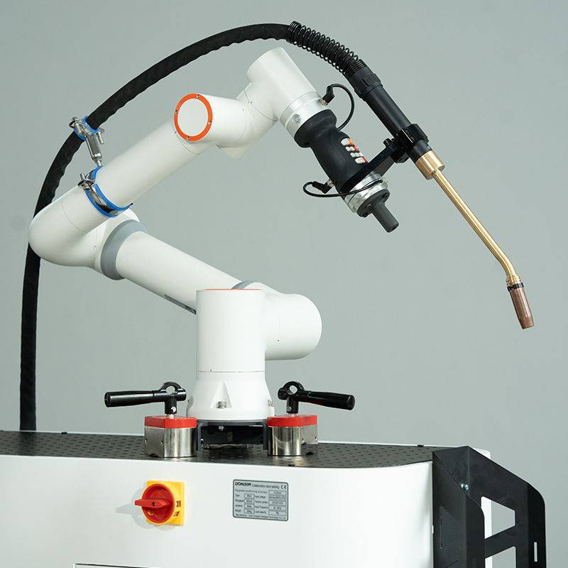
The “All-in-one” designation is not merely a marketing term but a technical configuration. In our Dusseldorf trials, the All-in-one Cobot Station consolidated the power source, the wire feeder, the collaborative arm, and the interface controller onto a single, mobile 1200mm x 800mm footprint. In a dense German workshop, the ability to move the entire station via pallet jack to the workpiece—rather than moving a 5-ton structural beam to a fixed robot—is a fundamental shift in logistics.
2.2 The Human-Machine Interface in Collaborative Robotics
The success of Collaborative Robotics in this context relies on the “Lead-Through” programming method. During the evaluation, we observed that senior welders with zero coding experience were able to program a multi-pass 12mm fillet weld in under six minutes. By physically moving the arm to the start and end points and using the integrated teach pendant to set parameters (Voltage, Wire Feed Speed, Travel Speed), the “All-in-one” system bypassed the need for a dedicated robotics engineer. This democratization of automation is the core driver for adopting Collaborative Robotics in high-mix, low-volume Structural Steel welding.
3. Technical Performance in Structural Steel Welding
3.1 Heat Management and Air-Cooling Constraints
A significant point of technical contention was the use of an air-cooled system for Structural Steel welding. Typically, high-amperage structural work (above 300A) demands liquid cooling to prevent torch degradation. However, the Dusseldorf station utilized a high-velocity air-cooled torch designed for a 60% duty cycle at 350A.
Lesson Learned: We found that by optimizing the weave pattern and utilizing a pulsed-spray transfer mode, we could manage the thermal load effectively. The air-cooled system is advantageous in the field because it eliminates the risk of coolant leaks, which can lead to porosity in the weld pool and require costly rework. For S355JR steel sections, the air-cooled torch maintained a tip temperature below the critical threshold for contact tip wear, even during continuous 2-meter longitudinal welds.
3.2 Weld Quality and Penetration Profile
The consistency of the All-in-one Cobot Station outperformed manual operators in the consistency of the “throat” thickness of the fillet welds. In Structural Steel welding, over-welding (depositing more metal than required) is a common waste factor. The Cobot maintained a precise 6mm leg length with a variance of only +/- 0.2mm. This precision reduced wire consumption by 14% across the test batch of 50 rafters.
4. Practical Field Application: Dusseldorf Case Study
4.1 Shop Floor Integration
In the Dusseldorf facility, the All-in-one Cobot Station was positioned between two manual welding bays. The collaborative nature of the arm—specifically its force-torque sensors—allowed it to operate without a safety cage. If a worker accidentally bumped the arm while moving a steel plate, the system performed a Category 0 stop immediately. This safety feature is what enables Collaborative Robotics to exist in the “brownfield” environments of older European workshops where there is no room for dedicated robotic suites.
4.2 Throughput Analysis
We tracked the “Arc-on Time” (the actual time the machine is welding versus setup/cleaning).
- Manual Welder: 35% Arc-on time (due to fatigue, helmet adjustments, and repositioning).
- All-in-one Cobot Station: 82% Arc-on time (sustained over an 8-hour shift).
The bottleneck shifted from the welding process itself to the “fit-up” and tacking process. To address this, we implemented a dual-station setup where the operator tacks one assembly while the All-in-one Cobot Station completes the Structural Steel welding on the second assembly. This “leapfrog” workflow maximized the utility of the collaborative system.
5. Technical Challenges and Lessons Learned
5.1 The “Dirty” Power Challenge
One unforeseen issue in the Dusseldorf industrial zone was electromagnetic interference (EMI) from neighboring heavy machinery. The All-in-one Cobot Station required a stabilized power input to prevent “ghosting” in the touch-sensing logic. Lesson Learned: Always specify an integrated line filter for the station’s control cabinet when deploying in older industrial sectors to ensure the Collaborative Robotics sensors remain calibrated.
5.2 Wire Feed Consistency
Because the All-in-one Cobot Station is mobile, the wire spool is often moved. We noticed that if the spool was not properly tensioned after a move, the collaborative arm’s rapid movements could cause “bird-nesting” at the drive rolls. We solved this by installing a locked-tension spool hub, ensuring that the Structural Steel welding wire (1.2mm G3Si1) fed smoothly regardless of the arm’s orientation or the station’s location on the shop floor.
5.3 Gas Shielding in Open Environments
Dusseldorf workshops often have high-volume ventilation fans. Since Collaborative Robotics operates in open spaces rather than enclosed cells, cross-drafts can strip the shielding gas (M21 Ar/CO2 mix). We had to increase the gas flow from 15 L/min to 22 L/min and switch to a larger gas nozzle to maintain weld integrity. This is a crucial consideration for anyone moving Structural Steel welding from a manual booth to an open-floor cobot station.
6. Economic and Qualitative Impact
The return on investment (ROI) for the All-in-one Cobot Station at this site was calculated at 14 months. This takes into account the reduction in grinding time (due to zero spatter from the pulsed-arc settings) and the significant decrease in weld defects. Beyond the numbers, the “Collaborative” aspect improved morale. The welders did not see the cobot as a replacement, but as a “tool” that took over the most grueling, long-form Structural Steel welding passes, leaving the complex, multi-axis joins to their manual expertise.
7. Final Engineering Conclusion
The deployment in Dusseldorf confirms that the All-in-one Cobot Station is the optimal entry point for structural fabricators looking to modernize. By integrating Collaborative Robotics into the existing floor plan without the need for infrastructure overhauls, the facility achieved immediate gains in precision and throughput. The air-cooled approach, while requiring careful parameter management, provides the mobility and low-maintenance profile necessary for the rugged environment of Structural Steel welding. Future deployments should focus on standardizing the “tack-and-leave” workflow to fully exploit the 80%+ arc-on time potential of these units.
Signed,
Senior Welding Engineer, Field Operations
Dusseldorf Technical Bureau
-


LT240S tube laser cutting machine
-
LT120S tube laser cutting machine
-
Sale

Tank Fillet Welding Machine
Original price was: $1,000.00.$900.00Current price is: $900.00. -
Sale

MAK100 tube laser cutting machine
Original price was: $5,500.00.$5,000.00Current price is: $5,000.00. -

portable plasma air cutting machine
$1,200.00 -

2in1 fiber laser cutting machine
-

Air cooling Laser welding machine
-

HF h beam laser cutting machine
-

LT240 laser cutting machine
-

Laser welding machine
-


Cobot Welding Station
-

Gantry welding robot solution
-

Tracked Wheeled AGV Welding robot
-

LFH6020 Fiber laser cutting machine
-
LFP6020
-

robotic welidng machine
Advanced Fiber Laser Tube Processing Technology
Our CNC Fiber Laser Tube Cutting systems revolutionize metal fabrication by integrating high-precision cutting, punching, and profiling into a single automated workflow. Designed for versatility, this technology handles a wide array of profiles including Round, Square, Rectangular, and Oval tubes, as well as complex L-shaped and U-shaped channels.
- Precision Punching: High-speed hole punching with micron-level accuracy, eliminating the need for mechanical drilling or die-stamping.
- Complex Profiling: Advanced 3D pathing allows for intricate interlocking joints and specialized notch cuts, ideal for structural frames.
- High Material Efficiency: Intelligent nesting software minimizes scrap, reducing raw material costs across large production runs.
- Clean Finish: Delivers oxide-free, burr-free edges that require zero secondary grinding before welding.

Seamlessly processing multiple profiles with consistent precision.
Global Delivery & Logistics



From our high-tech manufacturing facility directly to your global site. PCL WeldCut ensures secure packaging, professional handling, and reliable international logistics to safeguard your equipment throughout the entire journey.