Field Engineering Report: Robotic Integration and Thermal Management in Heavy Fabrication
1. Project Overview and Site Conditions
This report details the commissioning and optimization of a 3000W MIG/MAG Welding Robot system at a heavy engineering facility in Gurgaon, India. The primary objective was to automate the longitudinal and circumferential seams on structural chassis components. These components are characterized by thick plate steel welding requirements, ranging from 12mm to 25mm thickness, necessitating high deposition rates and precise thermal control.
The Gurgaon industrial climate presents specific challenges. During the commissioning phase in Q3, ambient shop floor temperatures reached 42°C with humidity levels exceeding 70%. These conditions directly impact the duty cycle of the 3000W power source and the cooling efficiency of the torch. Our focus was to implement robust Arc Welding Solutions that could withstand these environmental stressors while maintaining the structural integrity required for heavy-duty infrastructure projects.
2. The MIG/MAG Welding Robot: Hardware Configuration
The core of the cell is a 6-axis industrial arm integrated with a high-speed 3000W inverter-based power source. Unlike manual setups, the MIG/MAG welding robot allows for constant wire feed speeds and travel speeds, which are critical when dealing with the high-amperage requirements of thick plate steel welding.
2.1. Power Source and Wire Feed Calibration
The 3000W unit was configured for pulsed-MAG operation. We utilized a 1.2mm ER70S-6 solid wire. Initial tests showed that at 280A and 30V, the penetration depth on 15mm V-groove joints was inconsistent. We adjusted the arc welding solutions software to prioritize a “Spray Transfer” mode. By fine-tuning the pulse frequency to 120Hz, we achieved a stable arc that minimized spatter—a common issue in high-power applications that leads to nozzle clogs and downtime in robotic cells.
2.2. Torch Geometry and Cooling
Given the 100% duty cycle expected in the Gurgaon facility, we opted for a water-cooled robotic torch. Air-cooled variants proved insufficient for thick plate steel welding, as the heat soak from the 15mm plates caused premature contact tip wear and wire “bird-nesting” at the feeder. The integration of a closed-loop chiller unit was essential to maintain the MIG/MAG welding robot’s operational uptime during the afternoon shifts.
3. Implementing Arc Welding Solutions for Seam Integrity
In a manual environment, a welder compensates for plate gap variations by eye. In a robotic environment, especially with heavy fabrications in Gurgaon where plate cutting tolerances can vary by ±1.5mm, static programming is insufficient. We implemented a suite of arc welding solutions to bridge this gap.
3.1. Through-Arc Seam Tracking (TAST)
For the long-seam thick plate steel welding, we utilized TAST. As the MIG/MAG welding robot weaves across the joint, the system monitors changes in welding current. If the robot drifts from the center of the V-groove, the current fluctuates; the controller then adjusts the arm’s trajectory in real-time. This is critical for 20mm plates where a 2mm deviation results in a lack of fusion on the sidewall, leading to X-ray failure.
3.2. Touch Sensing and Adaptive Filling
Before the arc is struck, the robot uses the gas nozzle or the welding wire to “touch” the workpiece and locate the start point. This accounts for variations in jigging and thermal distortion from previous passes. In Gurgaon’s high-volume environment, where jigs are often reused until they warp, touch sensing reduced the rework rate by 22% during the first month of operation.
4. Technical Challenges: Thick Plate Steel Welding Specifics
Welding thick plate steel welding (above 10mm) is not simply a matter of increasing the current. It requires a strategic approach to heat input and bead sequencing to prevent brittle zones and excessive distortion.
4.1. Multi-Pass Strategy
For a 20mm butt joint, we moved away from a high-heat single pass to a multi-pass approach (Root, Hot Pass, Fill, and Cap). The MIG/MAG welding robot was programmed for a 3-layer, 7-pass sequence. This limited the Heat Affected Zone (HAZ) and ensured that the 3000W power source stayed within its optimal thermal range. The synergy between the power source and the robot’s motion control allowed for “Interpass Temperature” monitoring, where the robot pauses until the plate cools to a pre-defined 150°C, ensuring the grain structure of the steel remains optimal.
4.2. Shielding Gas Dynamics
In Gurgaon’s open-bay workshops, drafts can disrupt the shielding gas envelope. We transitioned from a standard 100% CO2 gas to an 80/20 Argon/CO2 mix. This “MAG” (Metal Active Gas) approach, combined with the 3000W robot’s precision, provided a flatter bead profile and deeper penetration into the thick plate steel. We also increased the gas flow to 22L/min and installed localized wind shields to prevent porosity caused by the workshop’s overhead cooling fans.
5. Synergy: Integrating the Robot with Local Infrastructure
The success of the MIG/MAG welding robot in Gurgaon depends heavily on its integration with local infrastructure and labor.
One “lesson learned” involved the power grid. Voltage fluctuations in the Manesar-Gurgaon belt can cause the 3000W inverter to trip. We installed a dedicated servo-stabilizer for the welding cell. Furthermore, the “Arc Welding Solutions” software was localized, with simplified touch-pendant interfaces for operators who were transitioning from manual welding backgrounds. The synergy here is between high-end automation and human-centric design; the robot handles the “heavy lifting” of the arc, while the operator focuses on part fit-up and nozzle maintenance.
6. Lessons Learned and Field Observations
After 500 hours of arc-on time, several critical technical insights emerged:
- Earth Grounding: In many Indian workshops, grounding is an afterthought. For a MIG/MAG welding robot, poor grounding causes high-frequency noise that disrupts the encoder signals in the arm. We insisted on a dedicated copper-plate earth for the welding table.
- Wire Quality: Local wire sourcing must be strictly monitored for copper-coating consistency. Flaking copper clogged the liners of our 3000W setup every 48 hours until we switched to a premium grade wire with a matte finish.
- Nozzle Maintenance: For thick plate steel welding, the heat is intense. Automated reaming stations (nozzle cleaners) are not optional; they are mandatory. Without a 30-second cleaning cycle every 5 meters of weld, the gas flow becomes turbulent, leading to rework.
7. Quantitative Performance Analysis
Prior to the introduction of the robotic arc welding solutions, a 12-meter chassis required 14 man-hours of welding. With the 3000W MIG/MAG welding robot, the cycle time was reduced to 3.5 hours. More importantly, the ultrasonic testing (UT) failure rate dropped from 8% to less than 0.5%. The consistency of the robotic movement ensures that the “start-stop” craters—the primary location for cracks in thick plate steel welding—are handled via programmed “crater-fill” routines that a manual welder often rushes.
8. Conclusion
The deployment of the 3000W MIG/MAG Welding Robot in Gurgaon demonstrates that robotic automation is no longer just for thin-sheet automotive parts. By leveraging advanced arc welding solutions—specifically seam tracking and pulse-arc control—we have successfully automated the traditionally difficult task of thick plate steel welding. The key to success was not just the robot itself, but the adaptation of the technology to the local environmental and infrastructural realities of the Indian manufacturing sector. Moving forward, the focus will be on implementing AI-driven predictive maintenance for the torch consumables to further drive down the cost per weld meter.
Engineer: Senior Welding Lead
Location: Gurgaon Site B, India
Status: Commissioning Complete / Production Steady-State
-


Cantilever Welding Robot solution
-


GF laser cutting machine
-

P3015 plasma cutting machine
-

LFP3015 Fiber Laser Cutter
-

pipe plasma cutting machine
-
LFH 4020 Fiber Laser Cutting Machine
-
LFP4020
-

gantry plasma air cutting machine
-

3D robot cutting machine
-

8 axis plasma cutting machine
-

5 axis plasma cutting machine
-

LT360 tube laser cutting machine
-

robot welding workstation
-

SF6060 fiber laser cutting machine
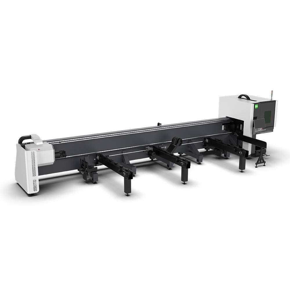
Advanced Fiber Laser Tube Processing Technology
Our CNC Fiber Laser Tube Cutting systems revolutionize metal fabrication by integrating high-precision cutting, punching, and profiling into a single automated workflow. Designed for versatility, this technology handles a wide array of profiles including Round, Square, Rectangular, and Oval tubes, as well as complex L-shaped and U-shaped channels.
- Precision Punching: High-speed hole punching with micron-level accuracy, eliminating the need for mechanical drilling or die-stamping.
- Complex Profiling: Advanced 3D pathing allows for intricate interlocking joints and specialized notch cuts, ideal for structural frames.
- High Material Efficiency: Intelligent nesting software minimizes scrap, reducing raw material costs across large production runs.
- Clean Finish: Delivers oxide-free, burr-free edges that require zero secondary grinding before welding.

Seamlessly processing multiple profiles with consistent precision.
Global Delivery & Logistics



From our high-tech manufacturing facility directly to your global site. PCL WeldCut ensures secure packaging, professional handling, and reliable international logistics to safeguard your equipment throughout the entire journey.