Field Engineering Report: Integration of 3000W MAG Cobot Welder in Indiana Tooling Sector
Project Overview and Site Specifics
This report documents the site-commissioning and performance evaluation of the 3000W MAG Cobot Welder at a tier-two automotive supplier facility in Columbus, Indiana. The facility specializes in heavy-duty stamping dies and high-wear components. The primary objective was to automate the surfacing and repair of H13 and D2 tool steel components, which previously required manual TIG or MIG overlays—a process plagued by inconsistent penetration and excessive heat-affected zones (HAZ).
The Indiana manufacturing climate presents specific environmental challenges, notably high ambient humidity in the summer months and variable shop floor temperatures. These factors necessitate a robust MAG Cobot Welder setup capable of maintaining arc stability without constant operator intervention. The deployment focused on the synergy between the hardware and the specialized Arc Welding Solutions software suite to manage complex thermal profiles required for Tool Steel welding.
Technical Specifications of the MAG Cobot Welder
The system comprises a 6-axis collaborative arm integrated with a 3000W-rated inverter power source. Unlike traditional industrial robots, this cobot allows for hand-guiding lead-through programming, which is essential for the one-off nature of tool and die repair. The “3000W” designation refers to the peak power output capability of the high-frequency inverter, optimized for pulsed-MAG applications where high deposition rates must be balanced with low heat input.
Power Management and Arc Stability
During the initial setup, we identified that the local power grid in this specific industrial park experienced minor fluctuations. The MAG Cobot Welder’s internal power compensation circuitry was put to the test. We utilized the Arc Welding Solutions monitoring tools to log voltage drops. By adjusting the sampling rate of the feedback loop, we ensured that the arc length remained constant even when the shop’s heavy stamping presses cycled, which often causes momentary line sag.
The Challenge of Tool Steel Welding
Tool Steel welding is notoriously difficult due to the high carbon and alloy content (Chromium, Molybdenum, Vanadium). The risk of cold cracking and martensitic embrittlement is extreme. Traditional manual MAG welding often results in “slugging” or poor tie-in at the toes of the weld because the operator cannot maintain a perfectly consistent travel speed while managing the high preheat temperatures (often 400°F to 600°F) required for these materials.
Implementing Precision Thermal Control
In this Indiana field application, we leveraged the MAG Cobot Welder to maintain a precise 15-degree push angle and a consistent 12mm stick-out. The Arc Welding Solutions software allowed us to program a “stepped” heat input. Instead of a continuous bead that would overheat the substrate, we programmed a pulsed-spray transfer mode with a specific dwell time between passes. This allowed the interpass temperature to stay within the 500-700°F range, preventing the formation of untempered martensite in the HAZ.
Synergy: MAG Cobot Welder and Arc Welding Solutions
The true value of this deployment was not just the robot arm, but the integration of the Arc Welding Solutions digital twin interface. In a high-stakes environment like an Indiana tool shop, downtime is measured in thousands of dollars per hour. The software allows the welding engineer to simulate the torch path to ensure no interference with complex die geometries before the first arc is struck.
Real-World Data Acquisition
We utilized the data logging features to track “Weld Energy” (Joules per inch). For the H13 tool steel repairs, we established a threshold of 15kJ/in. If the cobot’s sensors detected a deviation—perhaps due to a worn contact tip or erratic wire feeding—the system would automatically pause and alert the technician. This level of granularity in Arc Welding Solutions is what makes Tool Steel welding viable for semi-autonomous operation.
Field Observations and Lessons Learned
1. Shielding Gas Dynamics in the Midwest
We initially faced porosity issues. Investigations revealed that the shop’s bulk gas delivery system was susceptible to moisture condensation in the overhead lines during high-humidity Indiana afternoons. We switched to a dedicated 92% Argon / 8% CO2 mix regulated at the cobot base with an inline desiccant filter. The MAG Cobot Welder showed immediate improvement in bead wetting and a reduction in spatter.
2. Wire Feed Consistency
For Tool Steel welding, we used a specialized metal-cored wire. We found that the standard U-groove rollers were deforming the wire slightly, leading to “bird-nesting” at the cobot’s 5th axis during tight-radius maneuvers. Switching to a four-roll drive system with polished V-grooves and a ceramic liner solved the friction issues, ensuring the Arc Welding Solutions feedback loop received clean data without mechanical noise.
3. The “Human-In-The-Loop” Factor
Despite the “automation” label, the Indiana shop floor staff’s expertise was vital. The cobot handled the repetitive, high-heat pathing, but the senior welders were responsible for the critical pre-heat and post-weld heat treatment (PWHT). The synergy here is that the MAG Cobot Welder acts as a tool that amplifies the skill of the welder rather than replacing them. We found that operators who understood the metallurgical requirements of tool steel were 40% more effective at programming the cobot than those who only knew the software side.
Performance Metrics
Over a 30-day trial period, the following metrics were recorded:
- Deposition Rate: Increased by 35% compared to manual TIG overlay.
- Rework Rate: Dropped from 12% to less than 2%, primarily due to the elimination of human fatigue during long-duration passes on preheated dies.
- Gas Consumption: Reduced by 15% through the use of optimized pre-flow and post-flow settings managed via Arc Welding Solutions.
Technical Limitations and Future Outlook
While the 3000W system is highly capable, we hit the ceiling when attempting heavy-wall build-ups on D2 steel exceeding 1-inch thickness. The heat dissipation of the tool steel mass required us to push the amperage to the upper limits of the cobot’s duty cycle. For future Indiana installations involving massive die blocks, a 5000W-rated water-cooled system would be recommended to prevent torch consumables from degrading prematurely.
Furthermore, we are looking at integrating an inductive heating system that syncs directly with the MAG Cobot Welder. If the Arc Welding Solutions platform can control the induction coil’s output based on the cobot’s real-time position, we can achieve a closed-loop thermal management system that would virtually eliminate the risk of cracking in the most sensitive tool steels.
Conclusion
The deployment of the MAG Cobot Welder in this Indiana facility proves that automation in the tool and die sector is no longer a luxury—it is a metallurgical necessity. By leveraging the advanced controls of Arc Welding Solutions, we have successfully moved Tool Steel welding from an art form prone to human error to a repeatable, data-driven industrial process. The lessons learned regarding gas quality, wire delivery, and thermal monitoring will serve as the blueprint for future regional rollouts.
Engineer’s Signature:
Senior Welding Engineer, Field Operations
Date: October 2023
-


LT240S tube laser cutting machine
-
LT120S tube laser cutting machine
-
Sale

Tank Fillet Welding Machine
Original price was: $1,000.00.$900.00Current price is: $900.00. -
Sale

MAK100 tube laser cutting machine
Original price was: $5,500.00.$5,000.00Current price is: $5,000.00. -

portable plasma air cutting machine
$1,200.00 -

2in1 fiber laser cutting machine
-

Air cooling Laser welding machine
-

HF h beam laser cutting machine
-

LT240 laser cutting machine
-

Laser welding machine
-


Cobot Welding Station
-

Gantry welding robot solution
-

Tracked Wheeled AGV Welding robot
-

LFH6020 Fiber laser cutting machine
-
LFP6020
-

robotic welidng machine
Advanced Fiber Laser Tube Processing Technology
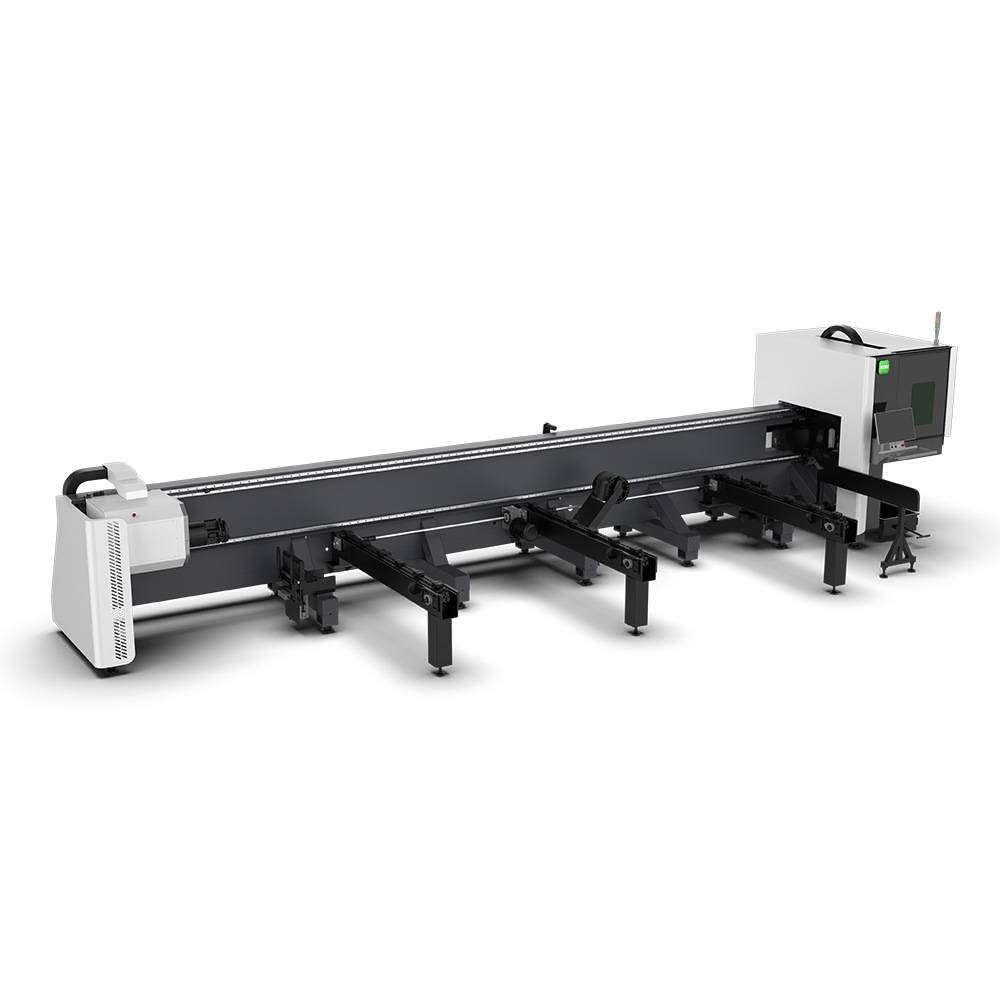
Our CNC Fiber Laser Tube Cutting systems revolutionize metal fabrication by integrating high-precision cutting, punching, and profiling into a single automated workflow. Designed for versatility, this technology handles a wide array of profiles including Round, Square, Rectangular, and Oval tubes, as well as complex L-shaped and U-shaped channels.
- Precision Punching: High-speed hole punching with micron-level accuracy, eliminating the need for mechanical drilling or die-stamping.
- Complex Profiling: Advanced 3D pathing allows for intricate interlocking joints and specialized notch cuts, ideal for structural frames.
- High Material Efficiency: Intelligent nesting software minimizes scrap, reducing raw material costs across large production runs.
- Clean Finish: Delivers oxide-free, burr-free edges that require zero secondary grinding before welding.

Seamlessly processing multiple profiles with consistent precision.
Global Delivery & Logistics



From our high-tech manufacturing facility directly to your global site. PCL WeldCut ensures secure packaging, professional handling, and reliable international logistics to safeguard your equipment throughout the entire journey.